Electrical & Firmware Design

Overview


The diagram to the left represents an overview of all the electrical components and how they are connected. The electrical enclosure at the base of the tripod is shown as well, housing most of the electronics in this system. The main sections include:

  • Power Management
  • Stepper Motors for Pan-Tilt Mechanism
  • Raspberry Pi for Tracking and Vision
  • RC Motor and ESC for Tripod Driving
  • Though all the connections shown were physically wired up, mechanical difficulties and time limitations ended up having us not use the RC Motor or the ESC in the final product. These components are also are grayed out with dotted lines in the diagram for clarity.

    Power Management


    Because our system contained many moving parts and expensive equipment, we wanted to be able to easily turn all motors on and off with one button and run everything risky off of our one 11.1V LiPo battery. The button we used was mounted on the side of the tripod leg for easy access and is pictured to the left. The button acted as a switch between the power line of the battery and the rest of the components being powered, so that when the button was turned off, the components would not be able to draw any power from the battery.

    In order to connect multiple wires to the LiPo battery, we had to solder two wires to a singular one coming from the positive and negative terminals of the battery. Each wire splitting off from each terminal would go to the corresponding positive/negative end in either our CNC Motorshield (and power the stepper motors) or our RC Motor ESC. A picture of the connections before we harnessed the wires to the tripod is shown to the left as well, with an arrow pointing to an example of such a split.

    Stepper Motors


    The system used two stepper motors to horizontally pan and vertically tilt the camera towards the detected person. The panning stepper is shown in the leftmost image-- it sits in the box under the tripod head and when the stepper rotates, the gears attached spin the tripod head containing the camera with it. The tilting stepper is pictured in the second photo, where it is attached to a gear that moves the camera up and down. Both steppers are driven by A4988 Drivers and a CNC Motorshield mounted on top of an Arduino UNO R3 with our LiPo battery supplying power.

    Raspberry Pi


    The Raspberry Pi was loaded with a program to track people's bodies and send commands to the Arduino via Serial communication through a USB cable. We mounted the Pi to the side of the tripod and powered it with a battery pack, and attached the Picamera near the top of the tripod head.

    RC Motor and ESC


    One of our stretch goals was to have the tripod drive on its own to physically follow a person as well. We used an RC Motor and a corresponding Electronic Stability Controller (ESC), using a separate Arduino to send motor commands to it. However, due to time limitations we were not able to integrate properly with the rest of the system. If you want to learn more details about electrical progress with the RC Motor, look into the Sprint 3 page.

    Stepper Motor Logic


    For the full firmware code, see the stepper_pan_tilt folder in our GitHub Repo.

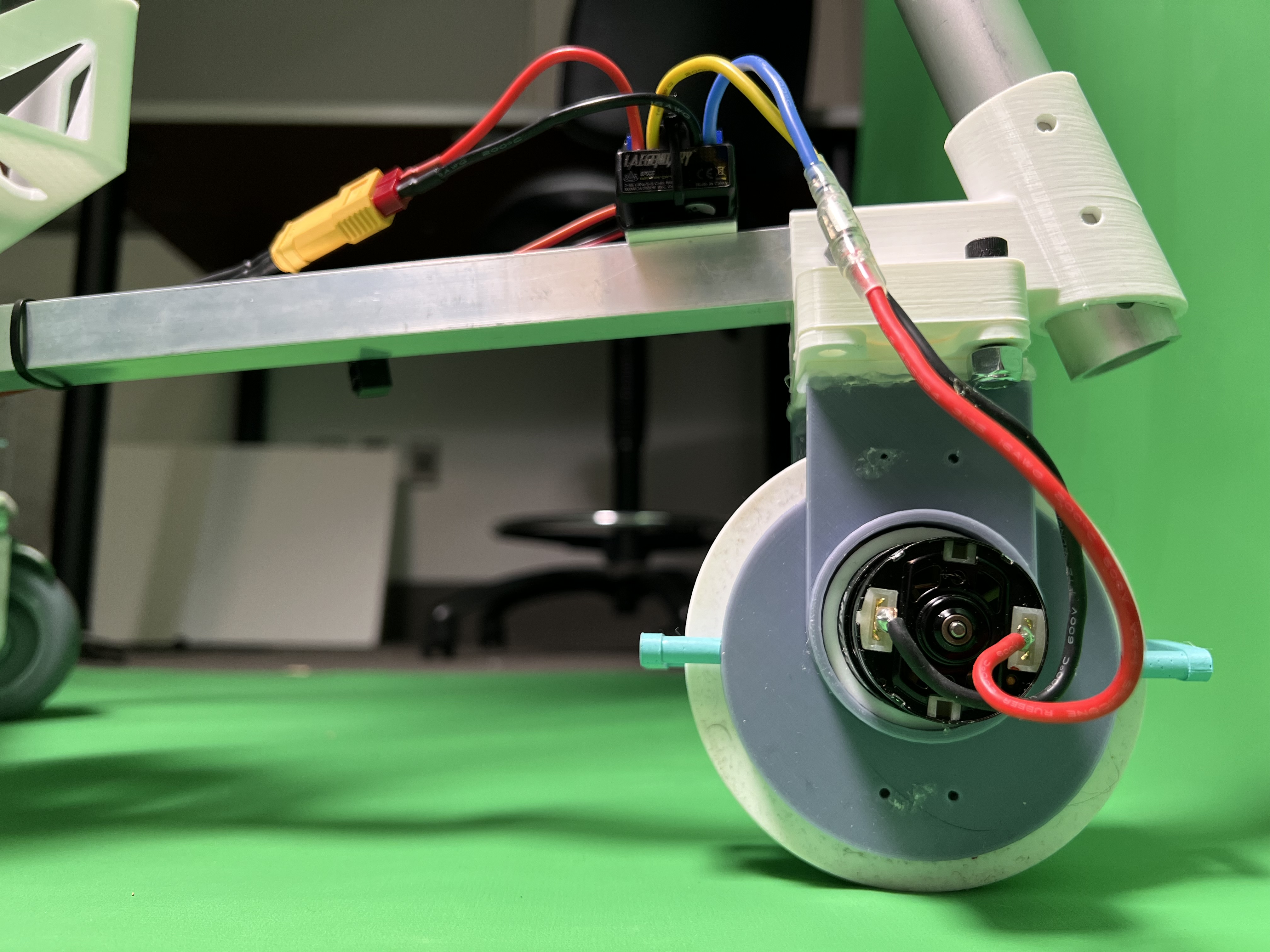
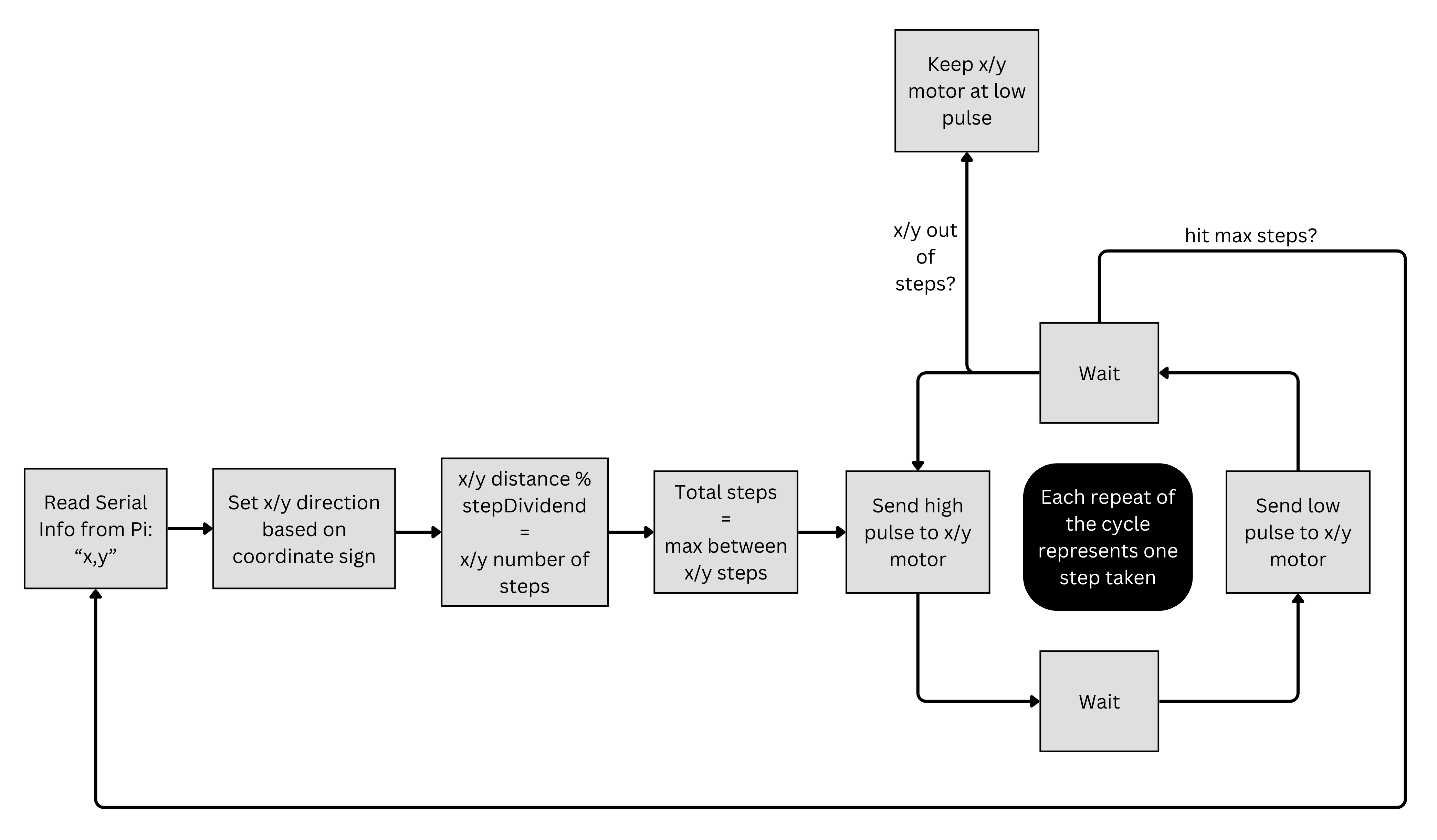
    Using our Arduino UNO R3, we sent commands to the x and y stepper motors to move the camera according to commands from the Raspberry Pi tracking program. We start by reading the x and y coordinate sent through Serial communication from the Pi-- based on the sign and value of the coordinates, we determine the direction and number of steps each motor must take. The number of steps is also reduced by a signDividend for each motor-- this value comes from tuning and makes sure the steppers move the appropriate amount and aren't stuck in a loop rotating and unable to read new Pi commands.

    The actual driving loop uses the maximum steps between x and y steps as a counter-- this enables us to move x and y motors in the same loop so the camera can pan and tilt at the same time. The process of stepping once involves sending a high pulse for a short amount of time, followed by a low pulse. Repeating this some number of times produces the same number of steps.

    After the driving loop is done, the steppers are set low and go back to waiting for new Pi commands.