Mechanical Design

Overview


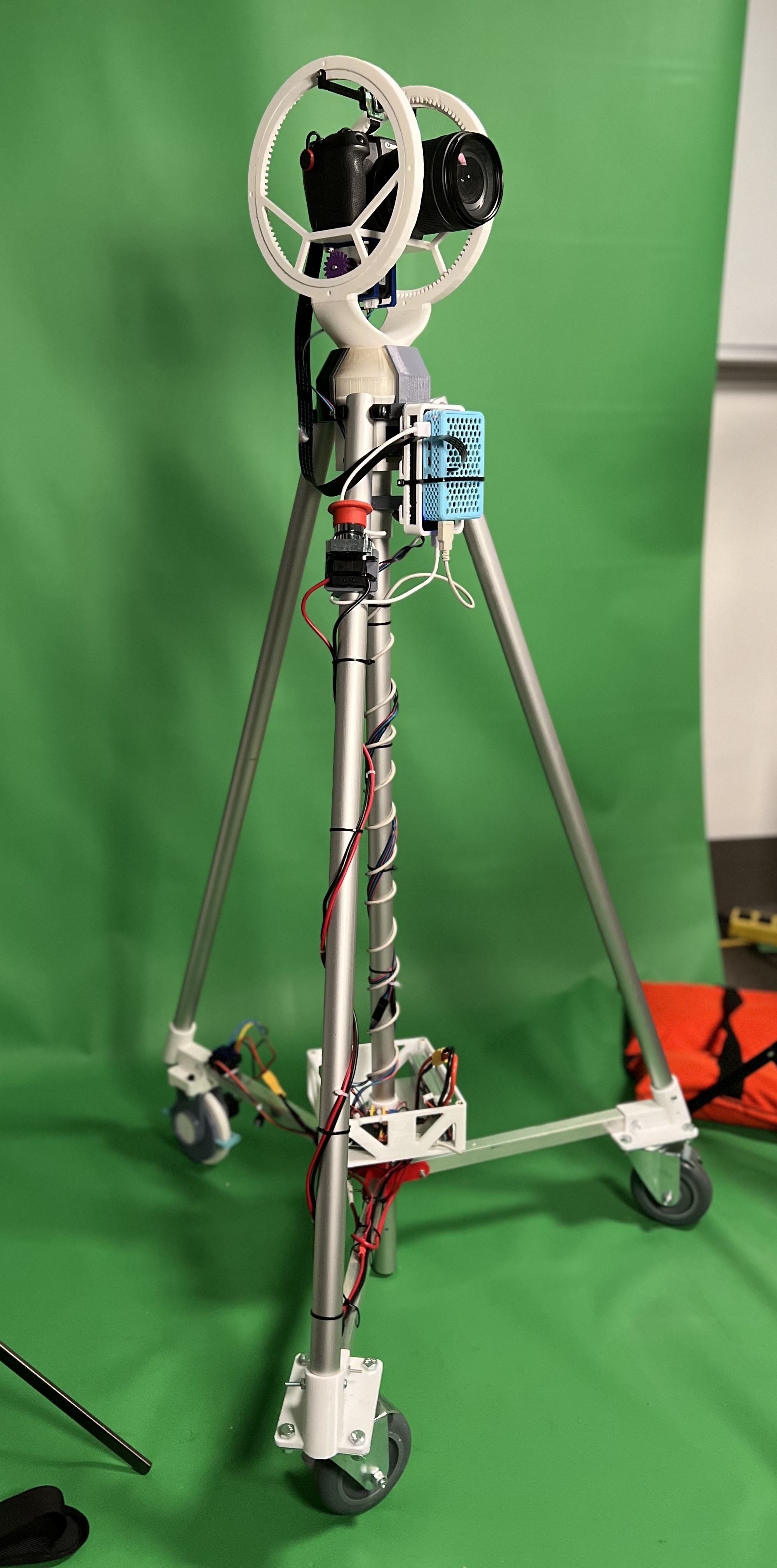
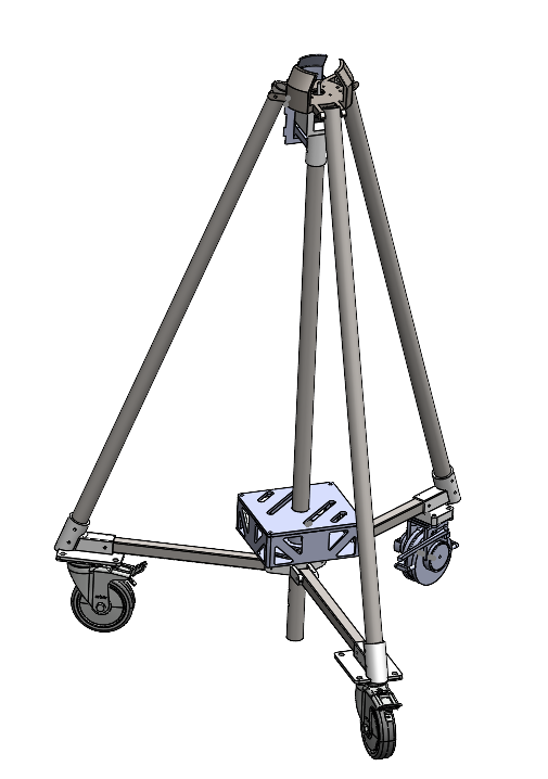
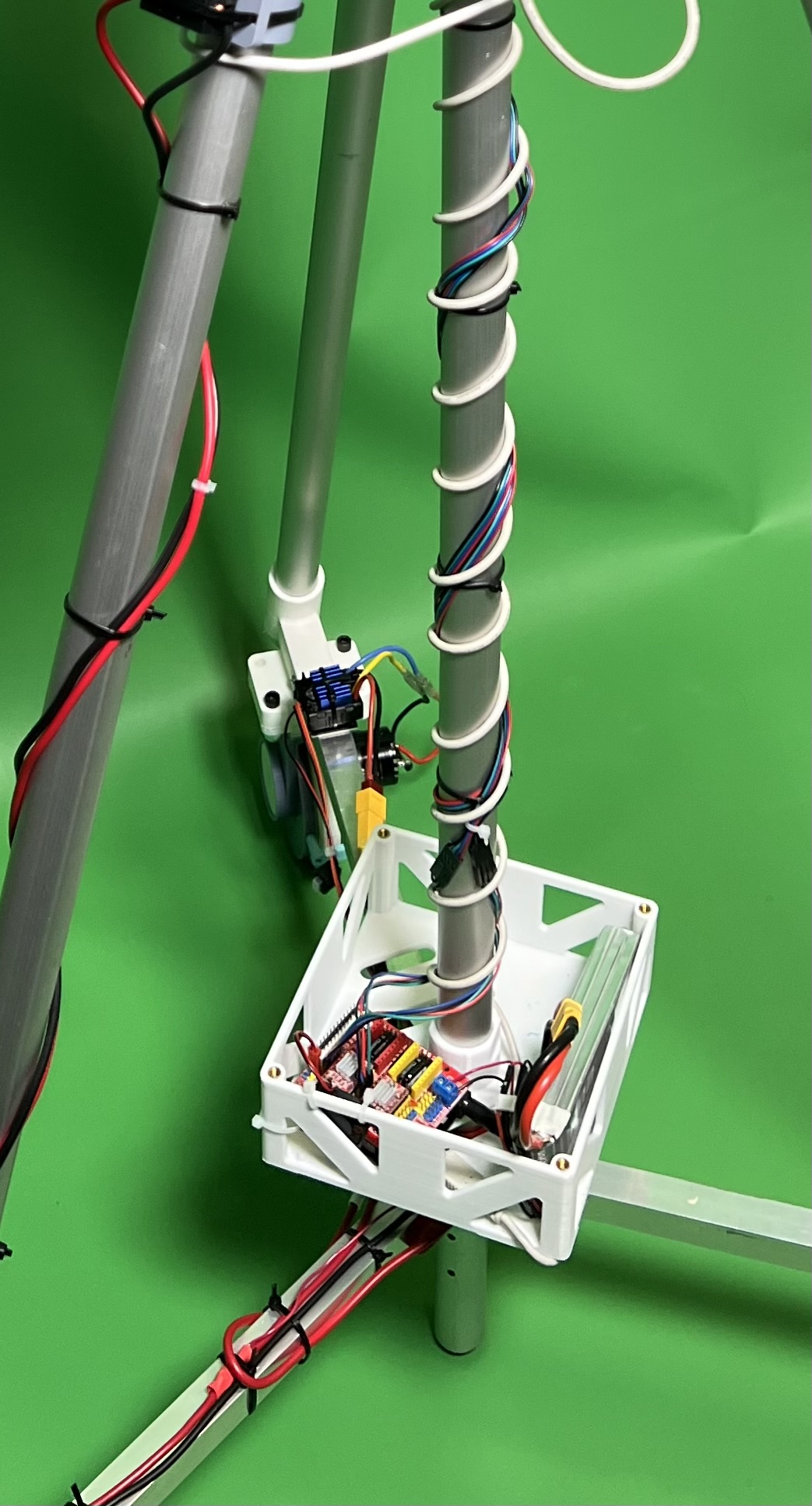
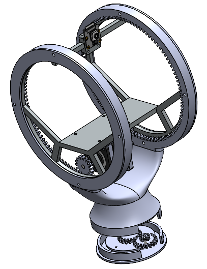
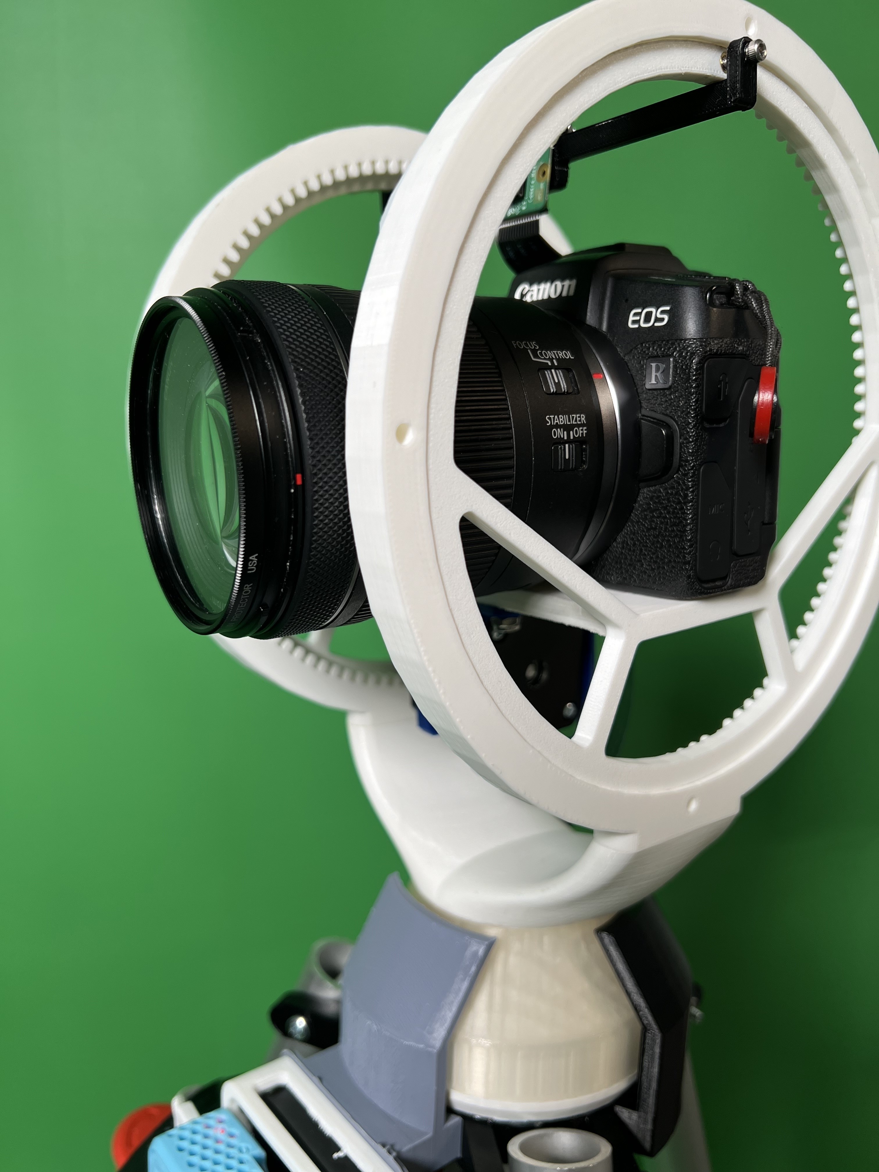
The mechanical setup comprised a tripod equipped with a wheel assembly, providing support for a pan-tilt mechanism that governed the camera's movements. A majority of the parts were 3D printed, which meant tolerancing was important and for gear functionality plastic part lubricant was necessary. Each component went through many iterations due to design changes and accompanying electrical aspects.

Tripod and Electrical Housing


The tripod featured three side legs, each connected to a wheel assembly, and a central leg, all constructed from aluminum circular tube stock to accommodate the stepper motor. To enhance stability, a triangular base made from rectangular aluminum stock was incorporated at the bottom. Additionally, when using a motorized wheel, a rectangular stock base was introduced to facilitate the passage of wiring from the electrical enclosure at the base, down the tube to that specific wheel.

Several electrical enclosures were integrated into the system, including one at the base, one connecting all tripod legs, and one on a side leg housing the start/stop button.

Pan-and-Tilt Mechanism


The pan-tilt mechanism employed gears for both panning and tilting movements. The stepper motor in the tripod assembly engaged with a gear in the pan-tilt base, which, in turn, interacted with subsequent gears to execute panning. For tilting, a suspended stepper motor with a gear was employed. As the gear ascended the structure with complementary gear teeth, the camera base would tilt either upward or downward.

Guards below the pan-tilt were also attached to the tripod top base in order to prevent the camera and tripod head from falling out.