
Electrical Diagram
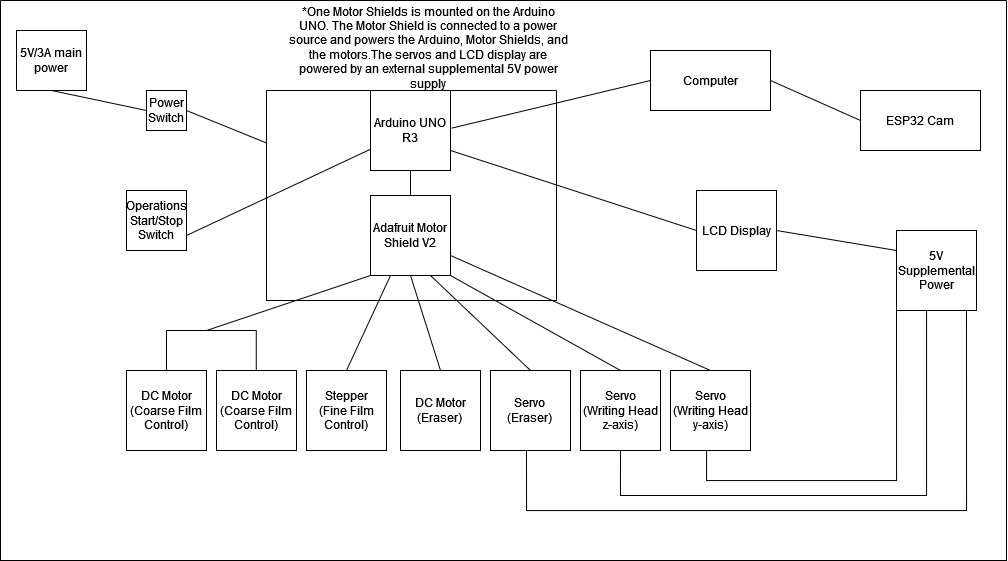
This diagram gives an overview of how the various electrical components are connected within the machine. Major components include the Arduino UNO R3, the Adafruit Motor Shield v2 and the computer. All the actuators (motors, servos, stepper) are connected to the Motor Shield and interface with the Arduino UNO so that they can be controlled. The computer is connected to both the ESP32 and the Arduino UNO so that new sketches can be easily uploaded and to allow for serial communication between the two microcontrollers.
Two power supplies are used, both 5V. One is used to power the Arduino and the DC and stepper motors while the second is used to power the servos and LCD panel. We chose to do this because servos connected to the Motor Shield are powered through the Arduino’s onboard power supply and powering three servos and/or the LCD panel off of it would overwhelm it and lead to unexpected restarts.
Microcontroller - Arduino UNO
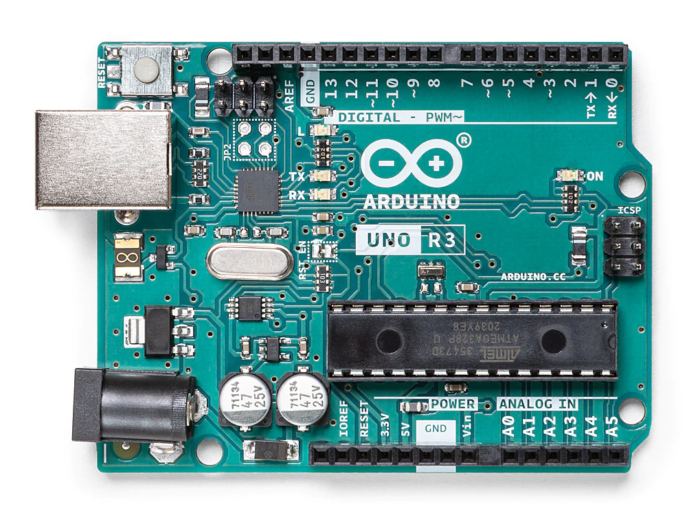
Controlling the motors is an important task for this machine, and it all happens on an Arduino UNO. The entire framework and codebase for state transition and critical operations on the Turing Machine are all executed using the Arduino. Arduino UNOs have a wide range of motors drivers that are compatible and have great documentation and support.
Microcontroller - ESP32-Cam
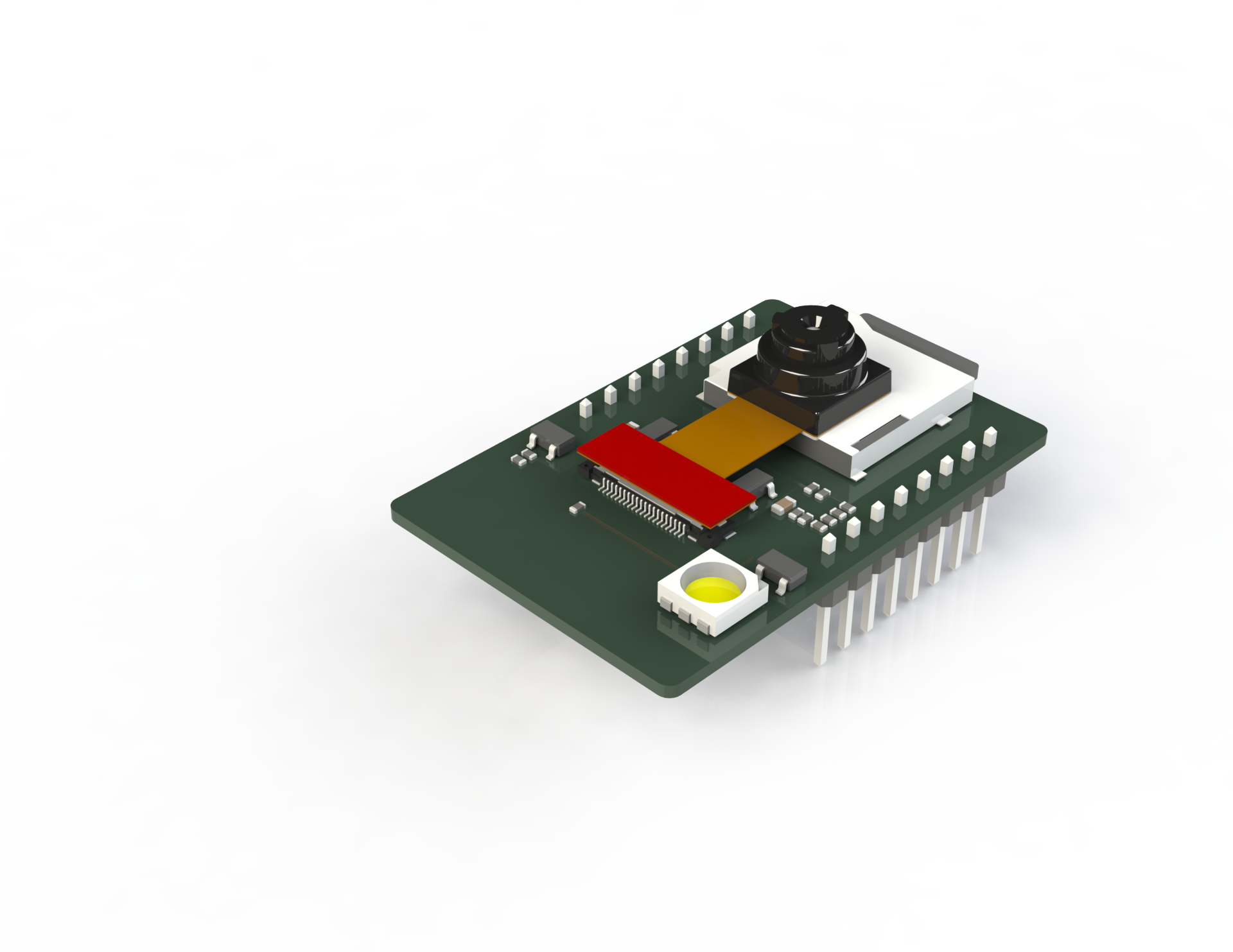
An ESP32-Cam has the computing power of an ESP32 but with a camera module. This microcontroller is the heart of the symbol recognition system and is powered by being plugged into a computer.
Motor Shield
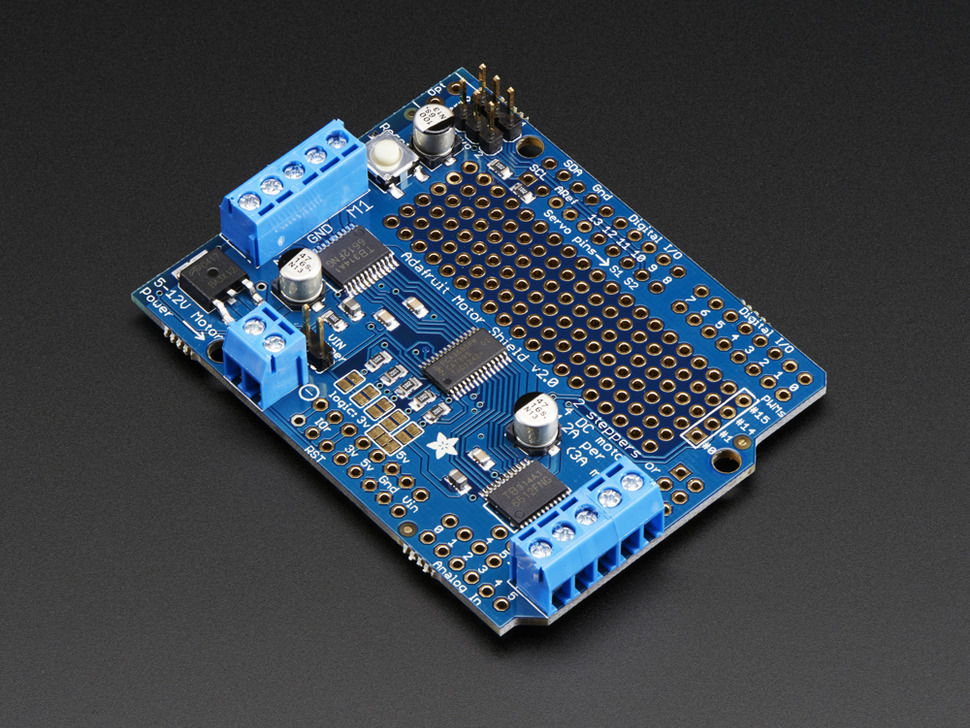
The AdaFruit Motor Shield v2 has the ability to control and power steppers, DC motors and servos, and stacks on an Arduino UNO. Using the Motor Shield prevents the need for several different driver boards and power management for the motors.
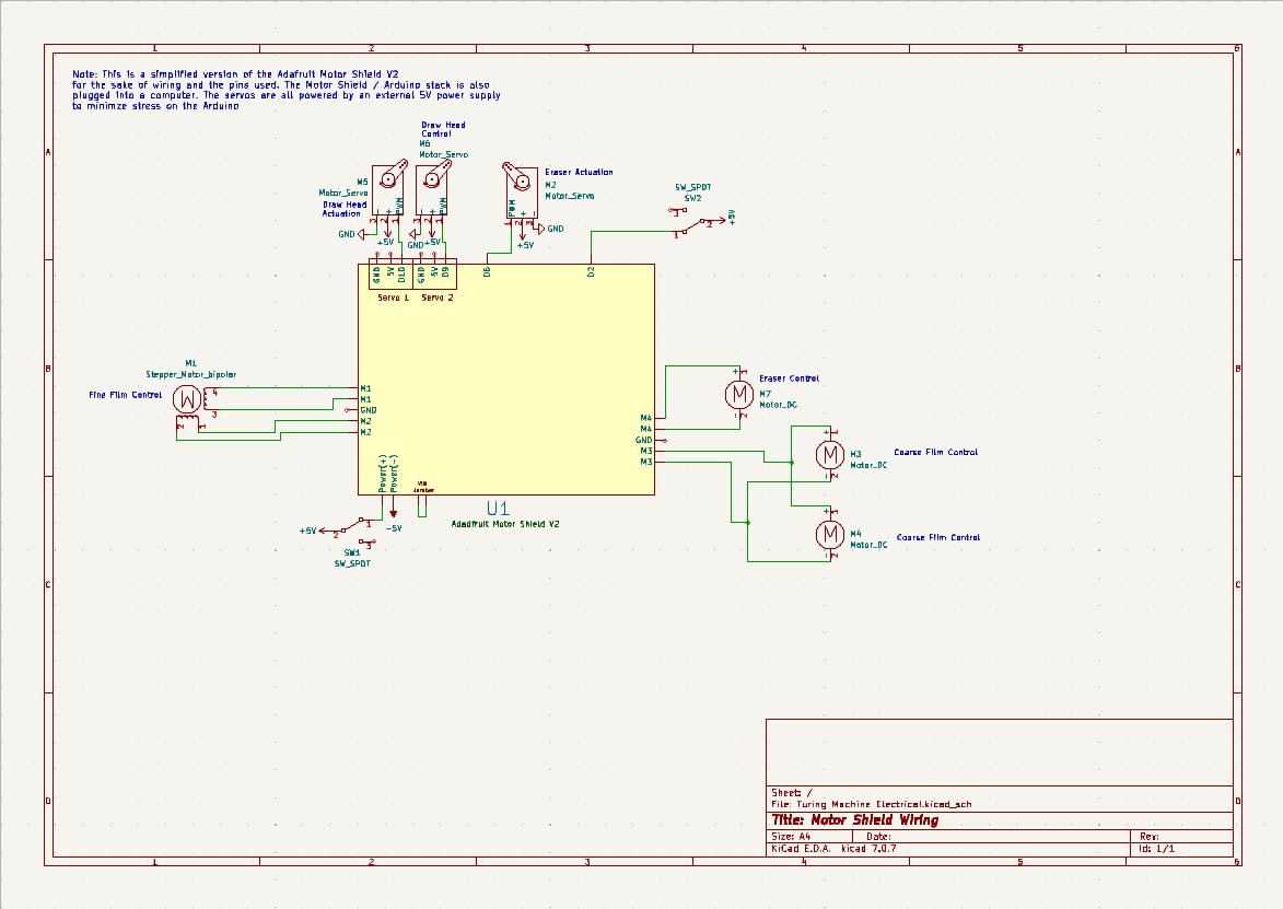
Motor Shield Wiring
This schematic is a wiring-level representation of how motors and components are wired to the motor shield.
Tape Actuation
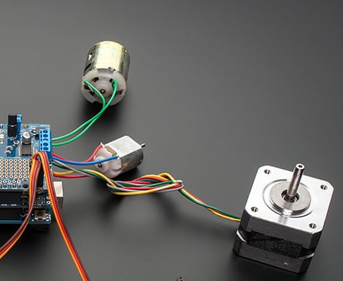
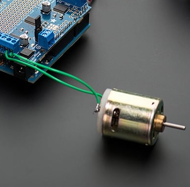
DC motors were used for the coarse control of the film movement. These motors unwind the tape from the spools to provide some slack for the fine control of the tape. These motors are controlled and powered by an AdaFruit Motor Shield v2.
A Nema 17 bipolar stepper motor controls the fine movement of the tape. This stepper has 1.8-degree step intervals and a total of 200 steps. The machine takes advantage of the small step intervals to move the tape in small amounts for smoother writing. This motor is controlled and powered by an AdaFruit Motor Shield v2.
Write Head
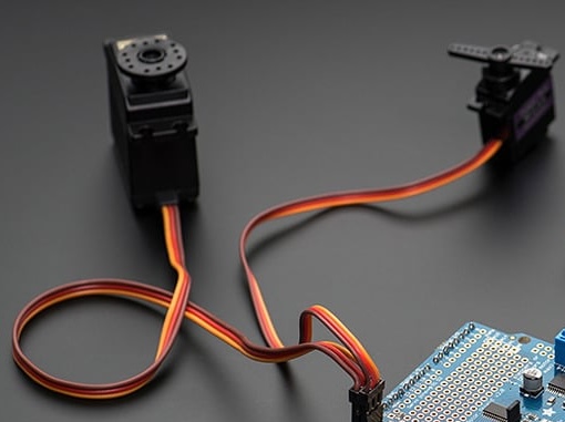
Servos control the vertical and horizontal motion of the marker. One actuates the use of the marker by lifting it up and down while the second servo moves the marker across the tape. This setup is optimized for drawing straight lines that are either directly parallel or perpendicular to the tape.
Actuating the tape is used for drawing symbols in coordination with the servos on the writing head. Lines parallel to the tape are created by actuating the marker downward and then moving the tape backward for forward motion. This utilized the fine movement of the tape actuation system.
Erase Head
The eraser head is actuated using a servo. In the un-actuated position, the eraser head is held above the tape by using the servos, and then when erasing needs to start, the servos lowers the eraser head down to touch the tape.
Once the eraser head has been actuated and is touching the tape, a DC motor starts spinning the eraser so that there is more surface to erase any symbols.
Once the eraser head is actuated and the eraser is spinning, the tape is moved across the eraser to erase any symbols on the tape. Using the tape actuation system allows for fine control of what parts of the tape come into contact with the eraser.