
CAD/Design
Throughout the project, we had a strong focus on creating and maintaining high-quality CAD for the Turing Machine. To do this, we implemented CAD standards at the beginning of the semester, such as: designing parametrically, using configurations whenever possible, file naming standards, and iteration/file management practices. We also utilized GitHub to share CAD. By maintaining an emphasis on these standards, we were able to manufacture many parts, if not perfectly, good enough to be functional on the first try. This greatly streamlined our design process and improved the overall quality of our assembly.
Write Head
The write head is one of our Turing Machine’s central systems. It is essentially a two-axis gantry, controlled by servo motors, that is responsible for writing symbols, primarily bits (so ones and zeros on the tape). Combined with the tape actuator, the write head essentially forms a mini three-axis gantry capable of writing any symbol.
Box
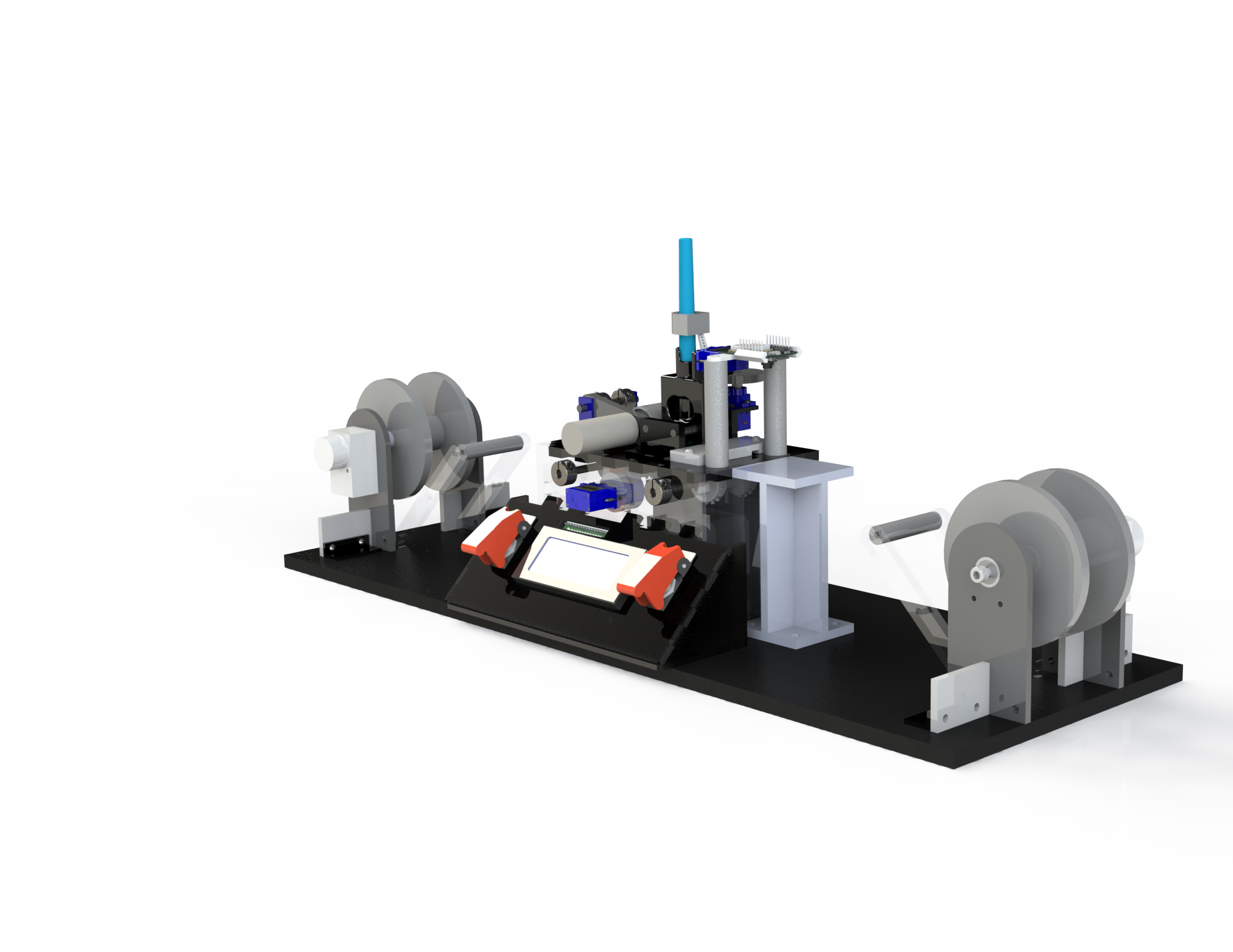
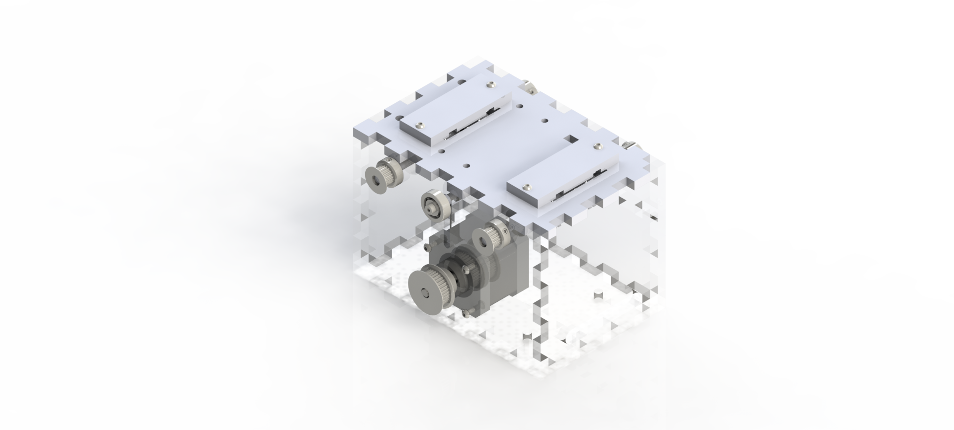
The heart of our Turing machine is the acrylic and Delrin box that houses our Arduino, drive shafts, stepper motor, and tape actuation system. In order to optimize for a low budget, acrylic was chosen for all sides of the box except for the top because the top was the only face requiring post-processing following laser cutting. Using Delrin for the top allowed us to tap holes, making the assembly process much smoother. The box is mounted to a CNC-milled plywood base plate with precise locating features for the box, tape runner, and tape spools.
Erase Head
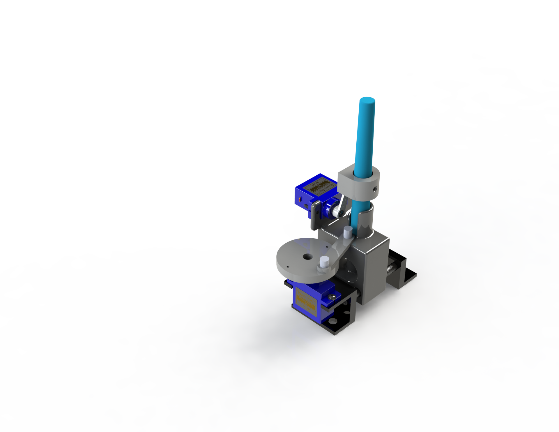
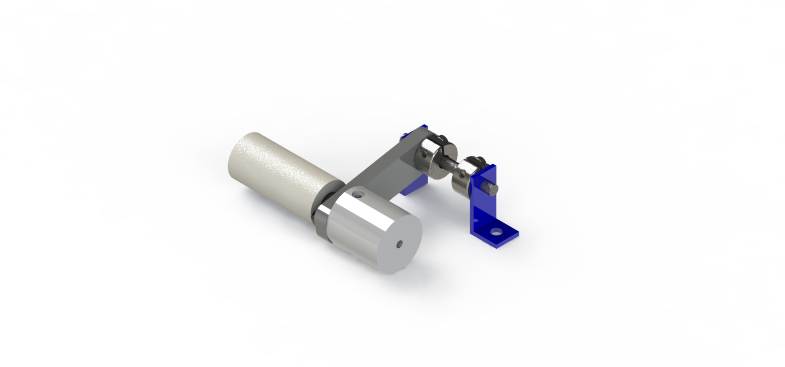
The erase head is another important component of the Turing machine, and it is responsible for erasing symbols drawn by the write head in order to write new bit-strings. The erase head consists of three major components: a rotating felt wheel powered by a DC motor, which is what makes contact with the ink, allowing it to be erased, a pivoting arm that supports the motor/wheel; and a servo with a CAM designed to actuate the head on the swivel to/away from the film.
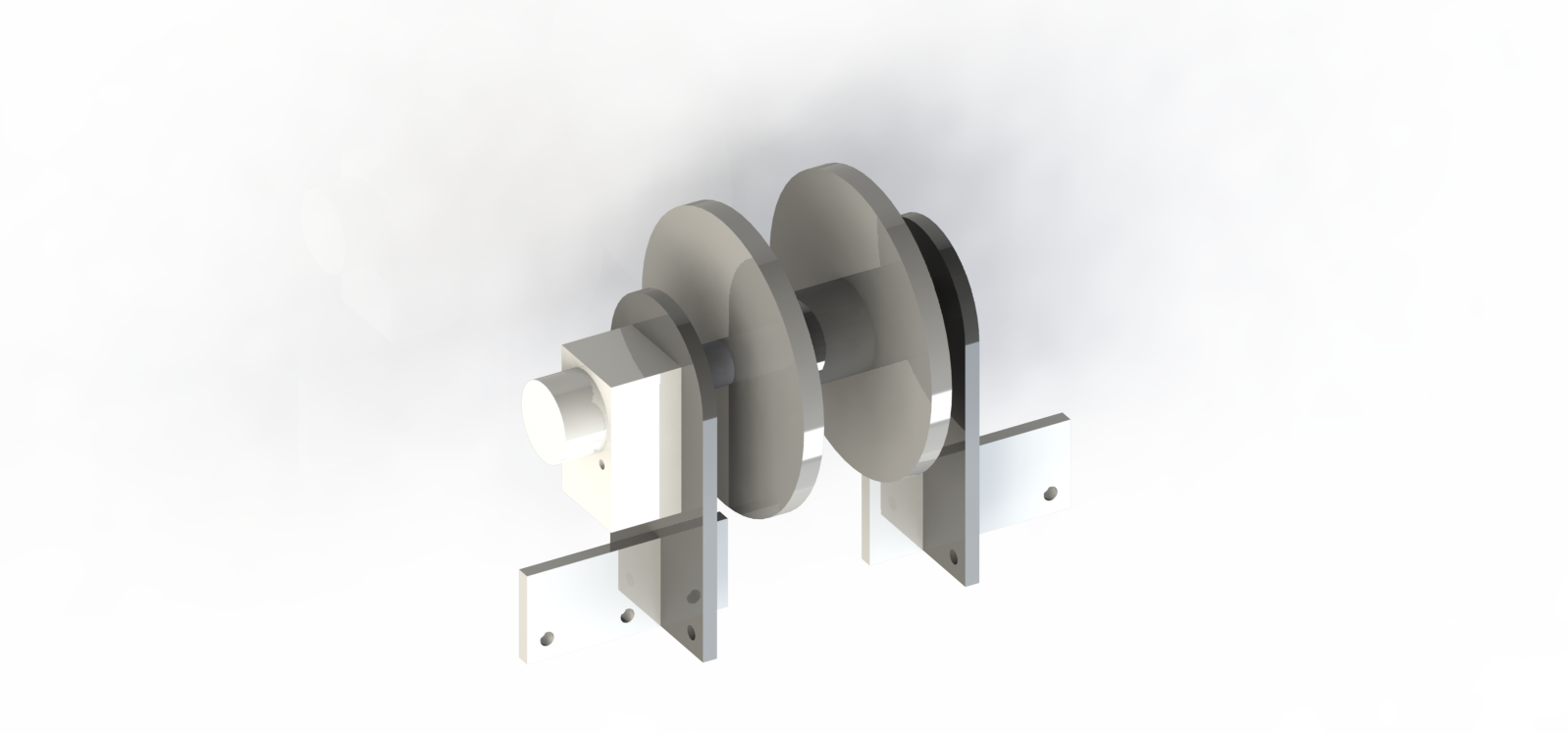
Tape Actuation
Tape actuation is arguably our Turing Machine’s most important system and was the first we designed. Without tape actuation, being able to write, read, or erase symbols is essentially useless. The tape actuation is what moves the plastic film leader along the track to/from the read, write, and erase stations. It also provides another axis of movement for the write head. The tape is actuated by a geared-down stepper motor. It is geared in such a way that 1 rotation of the shaft roughly corresponds to 1 symbol width. We also designed special sprockets in order to precisely fit and actuate our film. Finally, there are two Delrin plates positioned above the film to help maintain its tension and position relative to the sprockets.
Physical Film
For the film itself, we used a 35mm mylar film leader. We chose this because it has prebuilt groves designed for sprockets to aid in retention and actuation, dry-erase markers erase well from it and is reasonably priced. Also, the machine we were inspired by used a similar film leader.
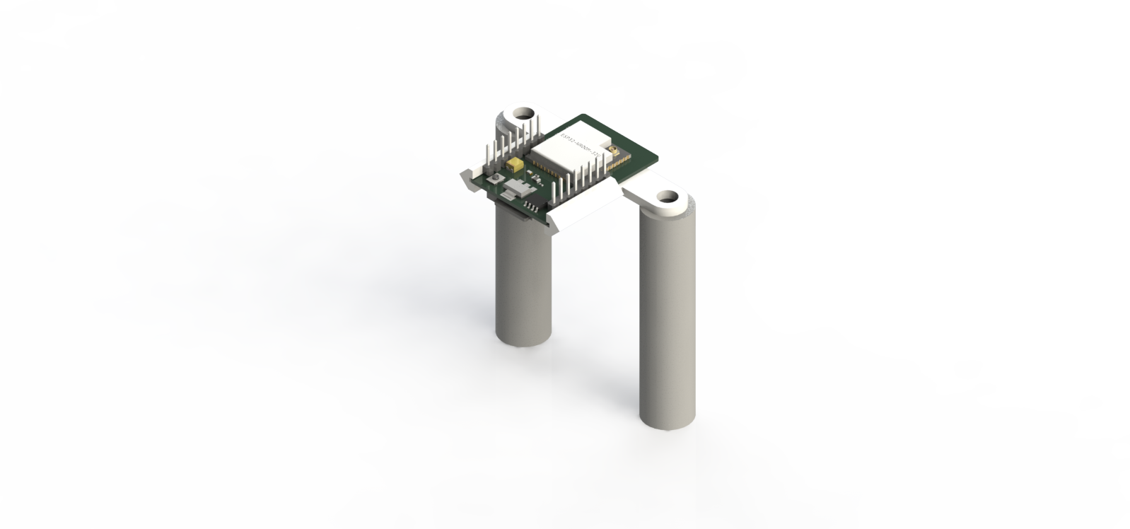
Camera Mount and Setup
The camera mount was designed to be easily modified in terms of z-height in order to compensate for other changes in the design. It consists of three components: a 3D printed mount that holds the edges of the camera’s PCB, a pair of standoffs that can be swapped to change camera height, and a simple sheet metal shroud to prevent glare and improve consistency of bit-string recognition.