Software Design
Logic & Control
Motor Control and Timing
All resistor measurement and dropping is coordinated based on the belt position, a variable that increments each time the belt advances by one module as detected by the limit switch). The bin width of exactly one module means that with each increment in belt position, one resistor can be measured and assigned to a bin, and up to fourteen resistors can be dropped via individual actuators triggering. The seamless integration of these actions is achieved using a three dimensional array. This array encodes the assigned bin for each measured resistor, the belt position at which it will be dropped, and the index for each bin dimension to accommodate additional resistors of the same category. When a given resistor is measured, all of these dimensions are computed so that, when it reaches the correct bin, a separate function can detect that the current the belt position matches its designated drop location and trigger the appropriate actuator. Notably, the array only needs to be large enough to accommodate all 14 bins and the number of belt increments between the measurement point and the farthest bin. Once the array is full, it can safely overwrite entries at lower indices because the resistors associated with those entries are guaranteed to have already reached and been dropped into their target bin.
Measuring Logic
The code for the measuring station is relatively straightforward. To calculate resistance, we use the equation:
Where Vnet is the supply voltage from logic power (approximately 5V), Rref is the known reference resistor selected by the multiplexer, and VR is the voltage across the unknown resistor R.
To derive the voltage across the unknown resistor, we use the conversion factor:
This is for our 10-bit AVR device (the same resolution as on Arduino Uno), where A is the raw analog-to-digital conversion value.
User Interface (UI)
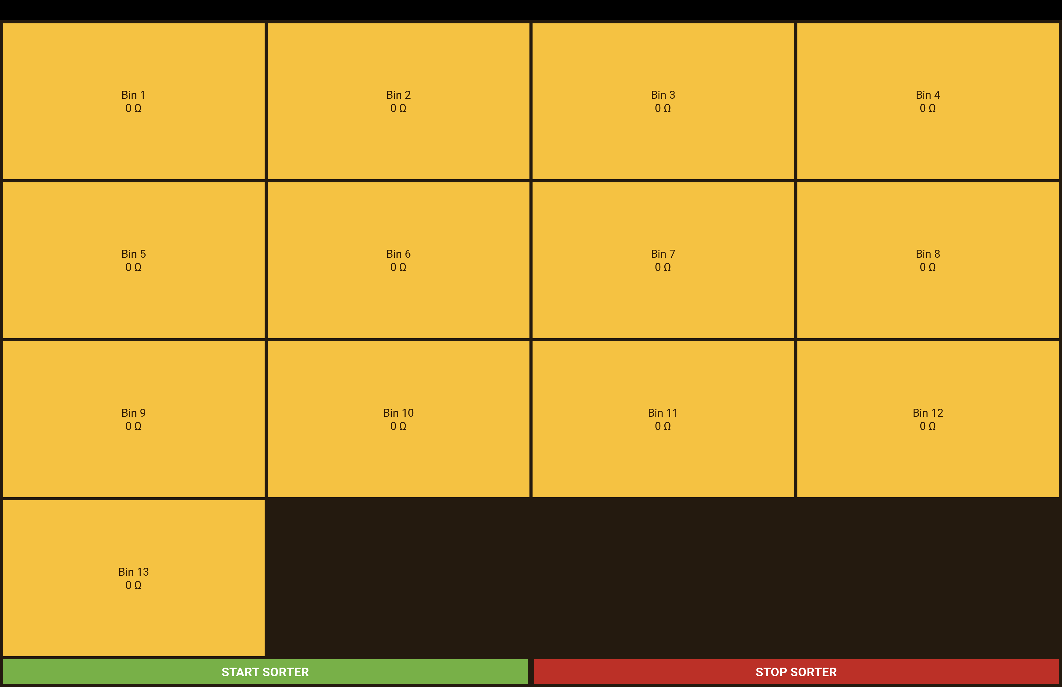
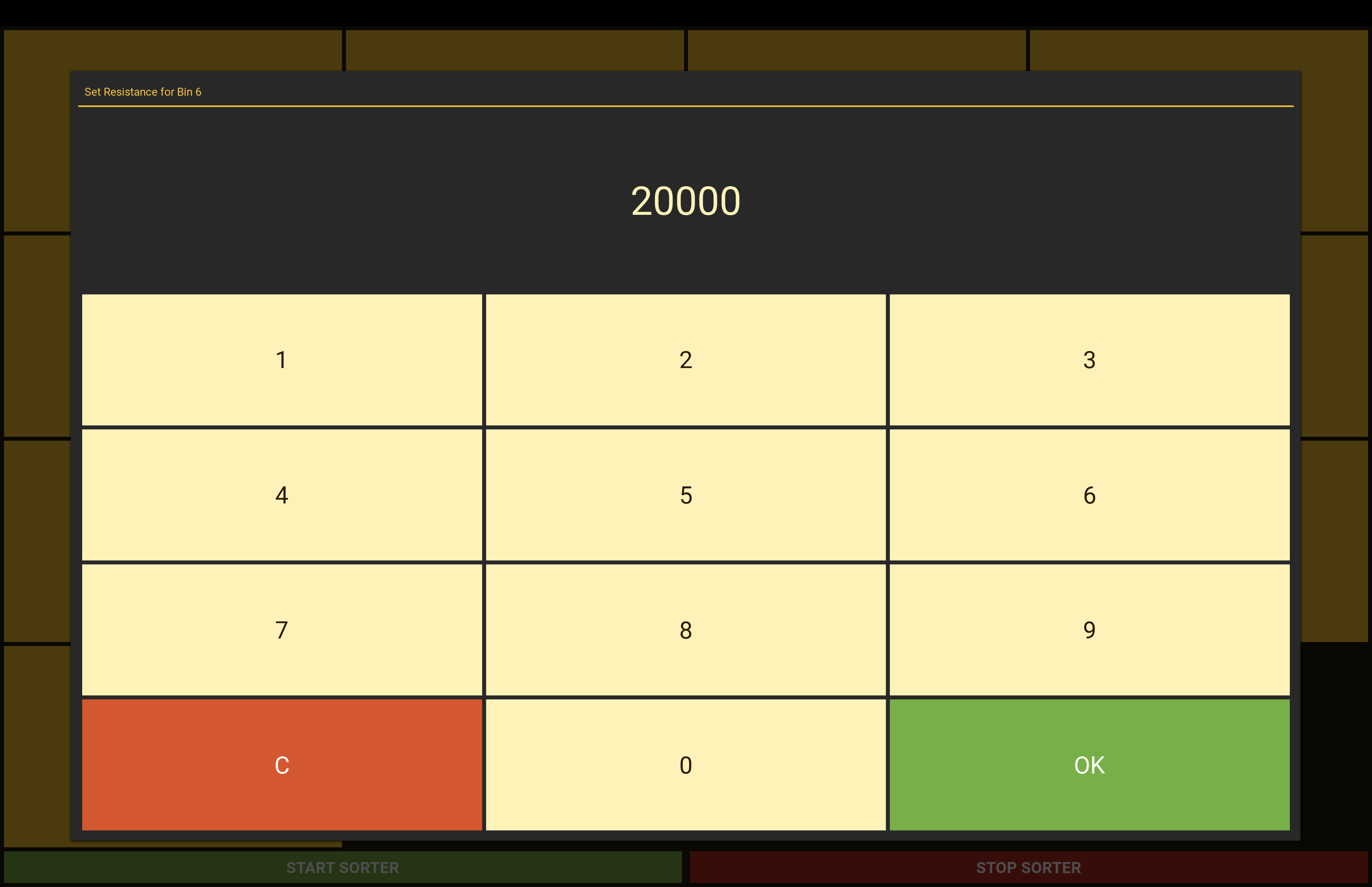
To allow the user to control which resistors are routed to each of the 13 bins, we use a touchscreen interface driven by a Raspberry Pi. The UI shows 13 boxes, each representing one bin, and uses a beehive-inspired color scheme that aligns with our overall design aesthetic. When the user taps a box, a numeric keypad appears, allowing them to input a new resistance value (in ohms) to assign to that bin Once the value is confirmed, the Raspberry Pi updates a JSON file that stores all bin states for future use, and a signal via an Arduino Nano to inform the PCB of the updated bin state. We use a JSON file to store the bin states so that user preferences persist across multiple runs, retaining the resistance values assigned to each bin from the previous session. We used Kivy, an open-source, cross-platform GUI framework, for UI development . We chose it because it enabled a relatively simple interactive GUI without requiring a full-stack web app to run on the Raspberry Pi OS.

Hardware-Software Bridge
We chose an Arduino Nano to bridge between the Raspberry Pi and the PCB because the Raspberry Pi operates at 3.3V logic, while the PCB requires 5V. Connecting these two directly over a communication interface like UART could exceed the Raspberry Pi’s 3.3V GPIO limits and risk permanently damaging its pins. Instead, the Arduino Nano connects to the Raspberry Pi via USB, and then interfaces with the PCB over its hardware Serial pins. This approach protects the Raspberry Pi’s GPIO pins from overvoltage damage and eliminates the need for an external logic level converter or similar voltage buffer, which could otherwise degrade signal integrity.
Design Considerations
Please see our "Electrical" page for the design considerations we made. Our software design decisions directly correlate to those made in the electrical subsystem.