Design Process and Sprints
Sprint 1: Resistance Module & Architecture
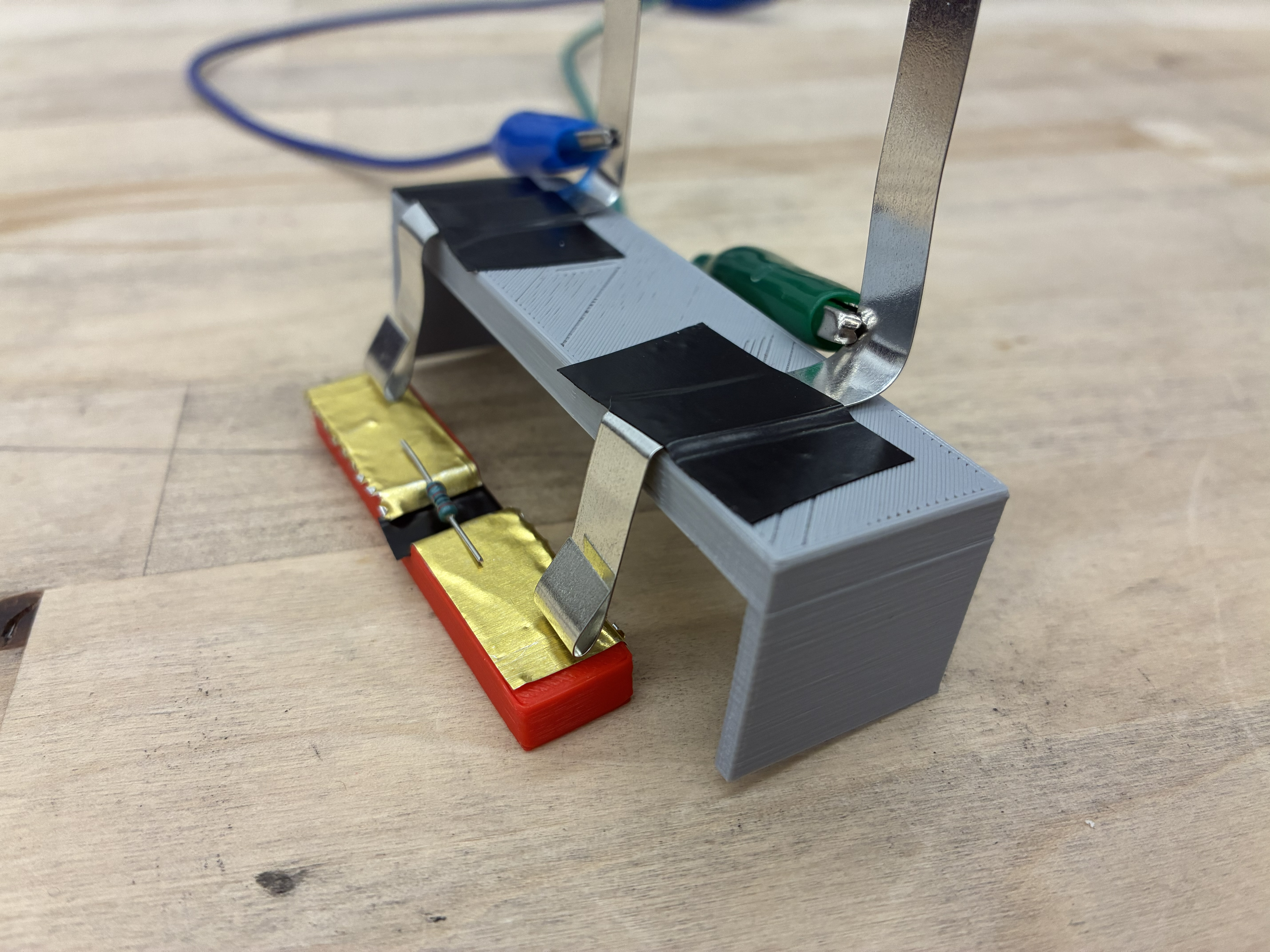
Goal: Solidify the overall system architecture and build a proof-of-concept resistance measuring station that fails for no more than 1 out of 100 resistors
Outcome: We successfully created the resistance measuring module using conductive copper foil and two metal prongs connected to a multimeter, and finalized concept CAD designs to begin development of the first mechanical subsystem iterations of our mechanical subsystems in Sprint 2.
Sprint 2: Scaled MVP Prototype
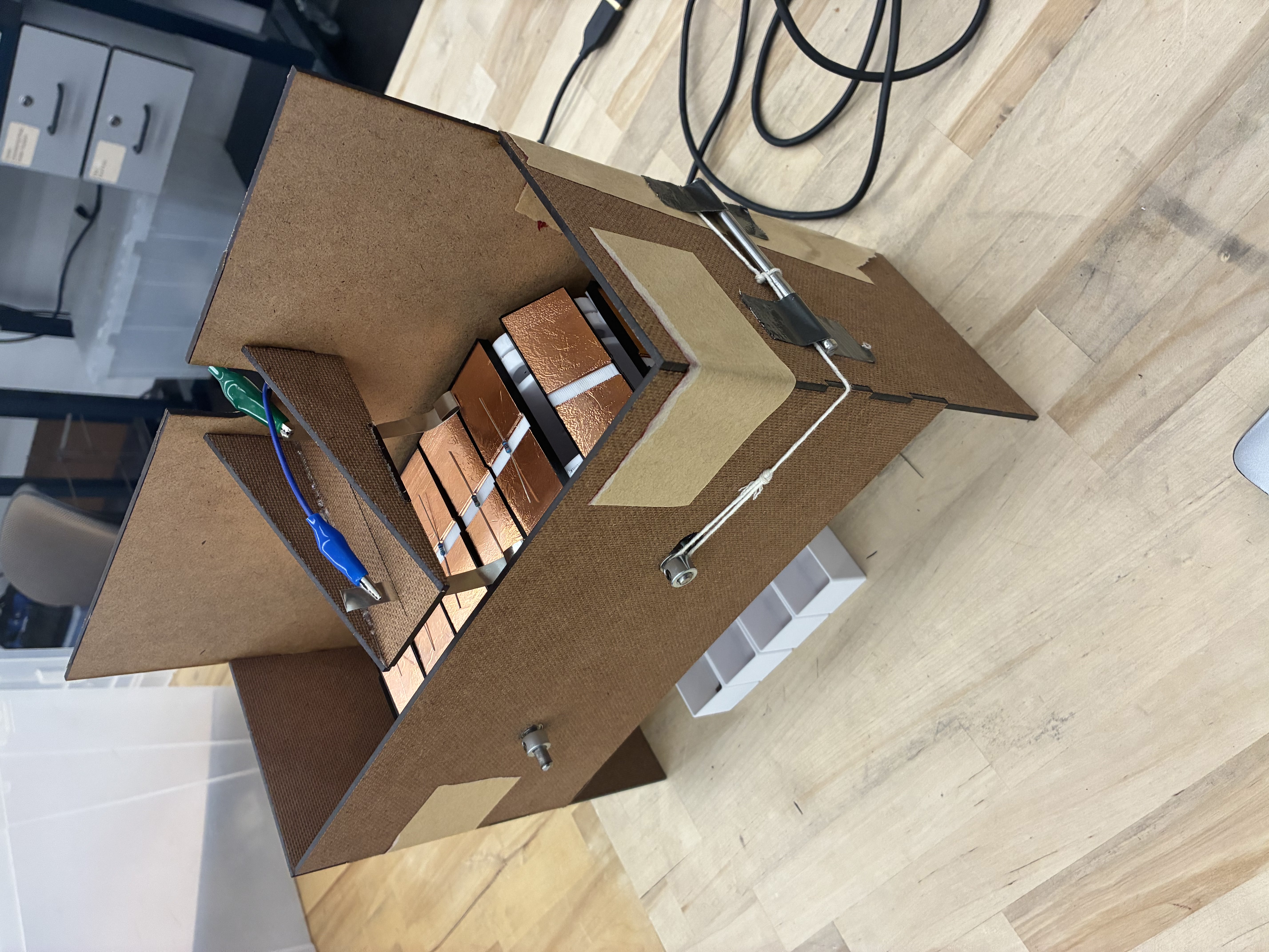
Goal: Create a fully functional, scaled-down version of our MVP.
For Sprint 2 we focused on creating a scaled down version of our final product. This included creating the tensioned conveyor belt, servo-actuated paddles, resistor bins, and resistance measuring station. In testing, we found that the intended stepper motor could not drive the conveyor directly and that servo-actuated paddles were ineffective for reliably sorting resistors into bins. We also began configuring the Raspberry Pi for the user interface.
Outcome: We were able to create a minimum viable product (MVP) of our resistor sorter with all the main mechanical and electrical components, albeit with a few flaws. This MVP gave us insight into improvements for themechanical system, and key design considerations for the electrical system.
Sprint 3: Subsystem Development
Goal: Fully develop each of the subsystems required for our resistor sorter.
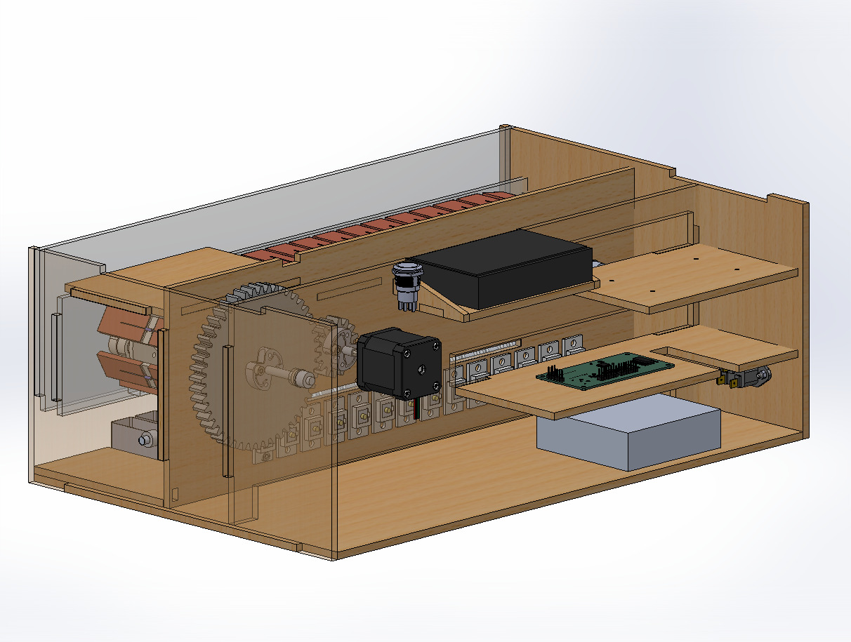
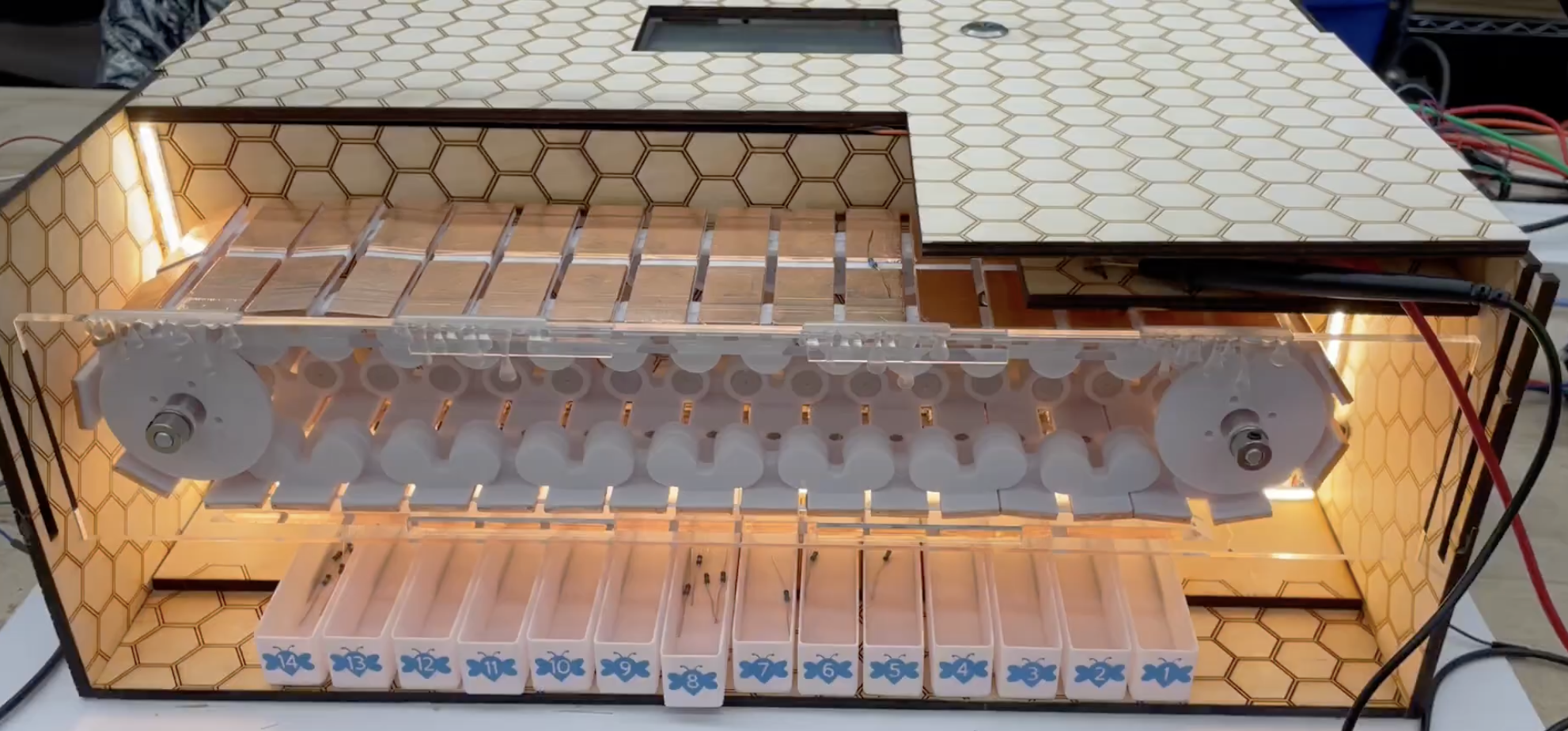
Mechanical: In this sprint, we focused on developing the final version of the mechanical and electrical subsystems. For the mechanical subsystems, we created a full CAD assembly of our final resistor sorter with a modular conveyor belt, linear-actuator actuated paddles, resistance measuring module, and custom housing. We also began to hone in on our design theme, adding numbered bee stickers to each of the resistor bins and adding a hexagonal raster to the housing panels.
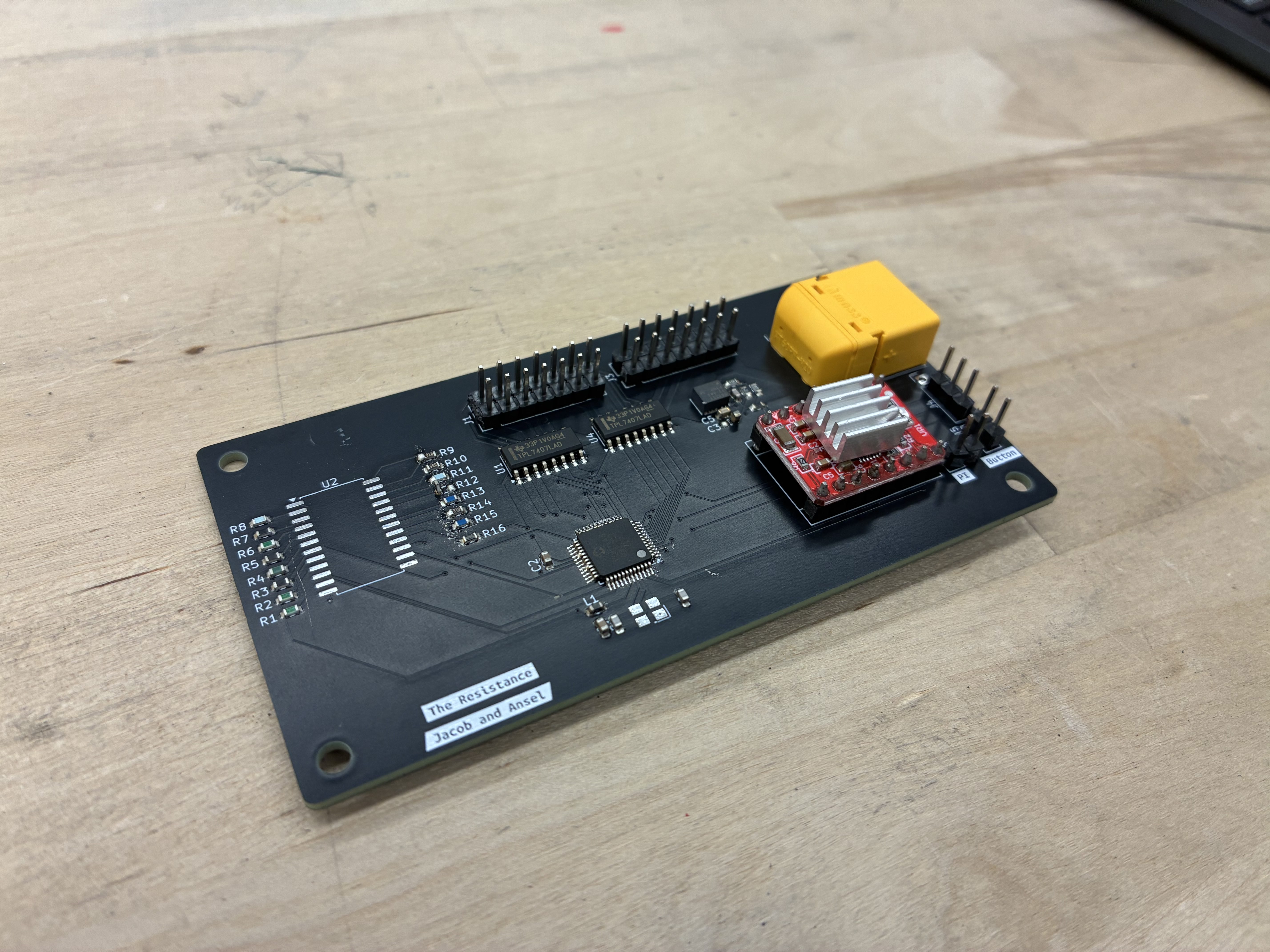
Electrical: For the electrical systems, we mainly focused on PCB assembly and electrical harnessing. During this sprint we mounted most of the devices to the PCB and managed wire routings to each of the devices, such as the stepper motor and linear actuators, ensuring they get the proper voltages they require. One setbacks we encountered here was that we received the wrong-sized mux, which prevented us from doing a full system test. Progress was also hampered by the fact that we had to create our stencil for the PCB out of mylar, which is a very difficult material to laser cut with.
Software: For the software systems, we created a fully functional version of the user interface. This included selectable bins that, when clicked, display a popup number pad where the user can input the desired resistance value.
Outcome: Most subsystemswere functioning but remained separate; the next steps were integration and establishing reliable communication between the Raspberry Pi, Arduino, and custom PCB.
Sprint 4: Integration & Final System
Goal: Finish building the final version of our resistor sorter, and complete integration of each subsystem.
Our goal for this sprint was to complete integration of the electrical, mechanical, and software subsystems together.
Mechanical: For the mechanical subsystem we focused on fabricating and assembling the final parts to construct the housing, conveyor belt, paddles, and resistor bins. We built on previously-designed parts by adding hexagonal textures and bee-shaped stickers to achieve our design goal. After the final assembly had been executed we mounted all the electrical components, including the stepper motor (and eventually DC motor), linear actuators, custom PCB, LCD screen, and on/off button.
Electrical and Software: For the electrical subsystem we focused on integrating the electrical and software subsystems together through a reliable communication system. To enable communication between the Raspberry Pi and the PCB, we used an Arduino as a bridge that would listen for commands sent by the Raspberry Pi (e.g. bin value changes, start/stop commands) and forward them to the PCB over serial.
Outcomes: We attempted to create a fully working final version of our resistor sorter, but we encountered some problems with our electrical subsystem such as brownouts and stepper motor failure. We discuss this in detail in the “Electrical” and “Mechanical” pages.