Sprint 1
Goal: Create a proof-of-concept prototype for our pin actuation design
Mechanical
Our main goal in Sprint 1 was to create proof-of-concept components for a single braille cell. We wanted to make sure that we could push up the pins to form braille dots, and use magnets to lock them into position. To accomplish these goals, we created two separate prototypes.
Our main goal in Sprint 1 was to create proof-of-concept components for a single braille cell. We wanted to make sure that we could push up the pins to form braille dots, and use magnets to lock them into position. To accomplish these goals, we created two separate prototypes.
Prototype 1
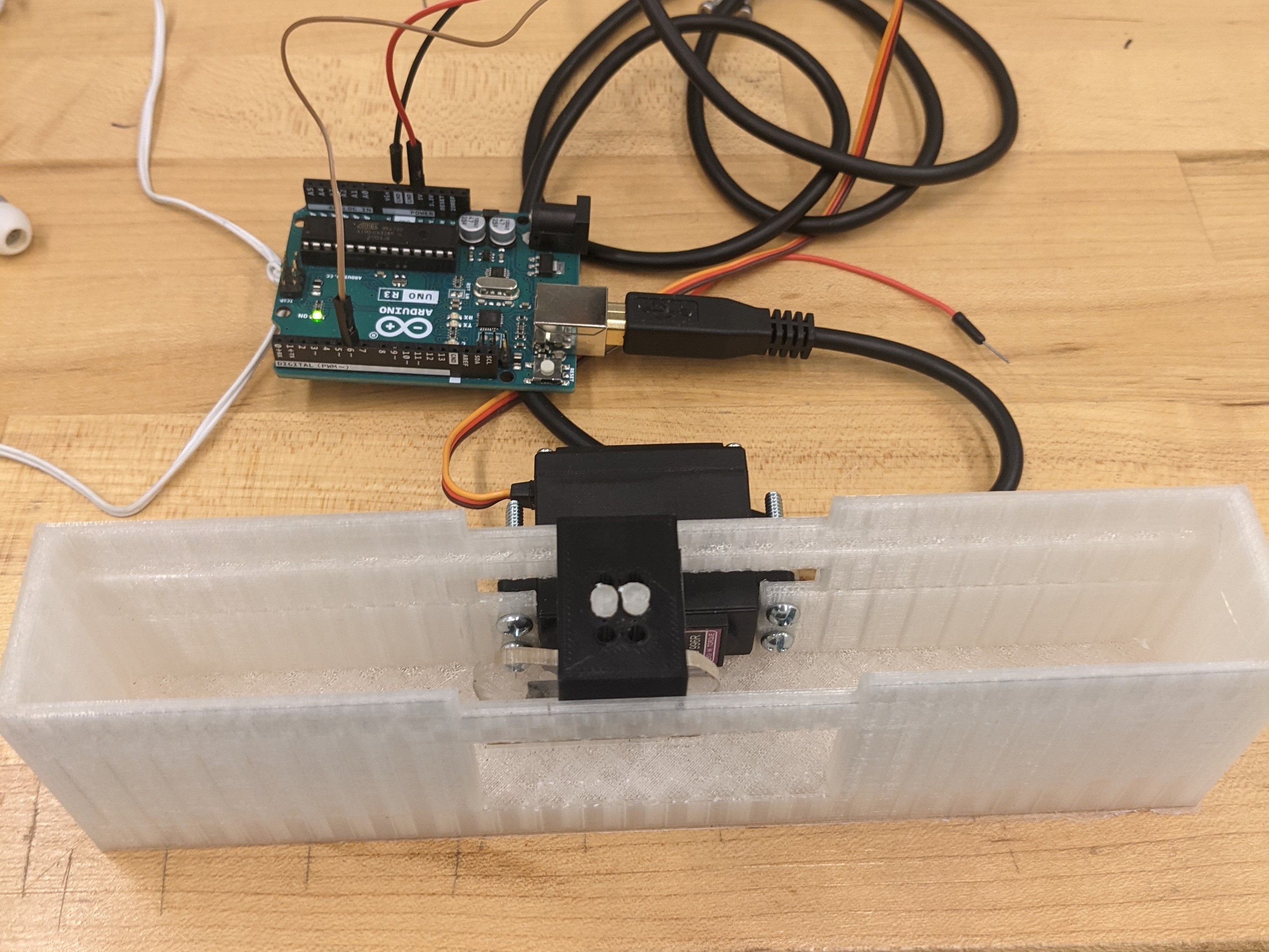
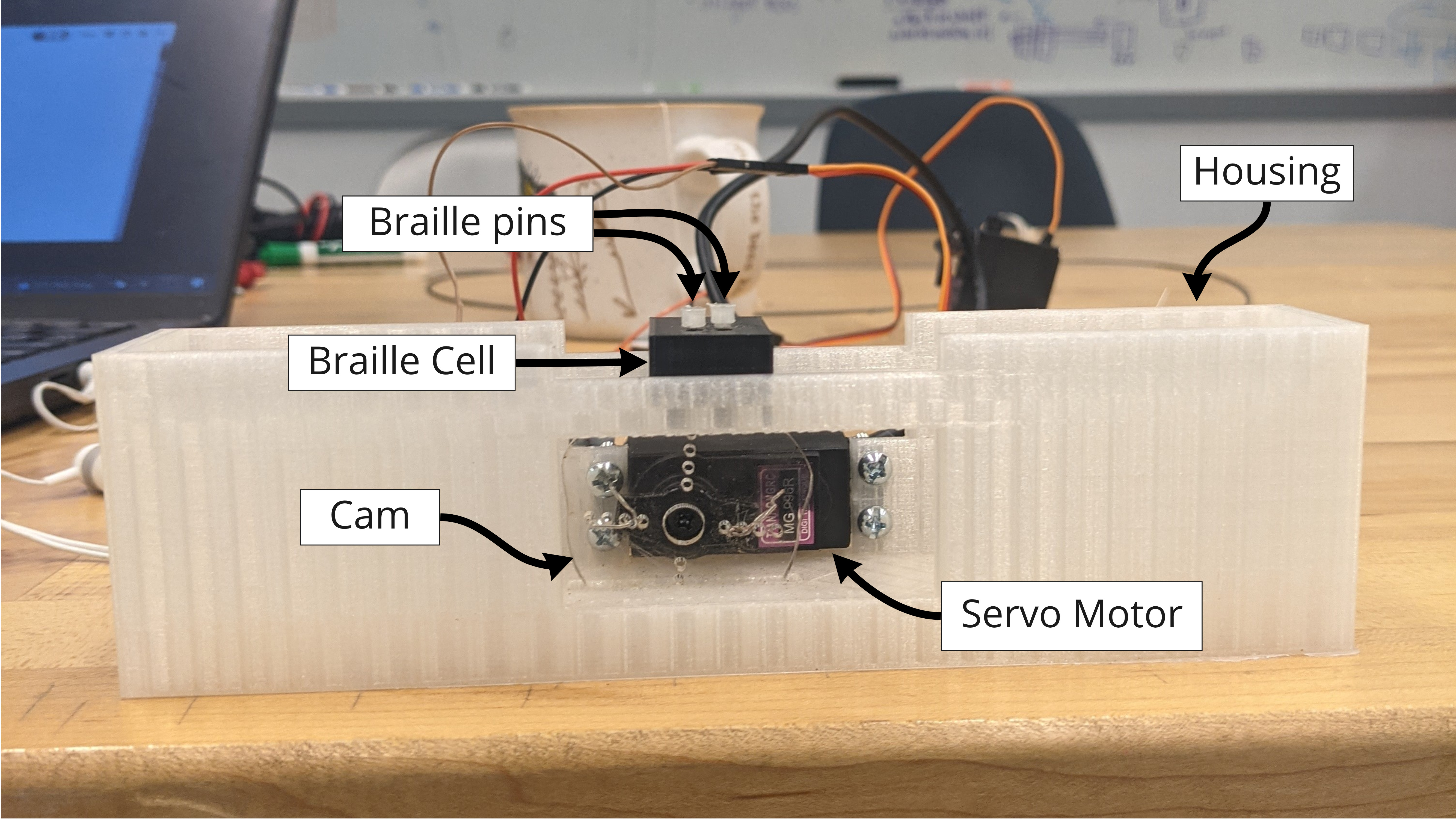
The first prototype was designed to test the feasibility of using a cam to push up a row of pins. It contained one braille cell (a 3D-printed block with six holes in it for braille pins), some braille pins (also 3D-printed), one cam (laser cut from clear acrylic) connected to a servo motor, and a housing that held everything together. Shown below is an image of the prototype with individual parts labeled.
As we made these prototypes, we realized that our 3D printers did not have high enough resolution to accurately print the pins. The pins that were printed had a tendency to jam in their holes. Looking forward, we decided to find a part to use for the pins that would move more smoothly in the cell holes.
To figure out the cam geometry, we made a few design iterations: first using cardboard and then using acrylic and the laser cutter so we could test a number of designs at one. The cam design shown in the prototype above has a 4mm travel distance, which was enough to move the pins up.
We decided to focus on braille cells with a 2x3 dot pattern, instead of the 8-dot pattern (2x4) often used in refreshable braille displays (Wikipedia - Braille). Our design doesn't allow us to properly utilise the extra row that's used to indicate cursor position and other information about interacting with a webpage.
Maintaining the proper dimensions for a braille cell is crucial to reader comprehension. However, braille is very small. To work around this, we decided to scale up the cells and related components by a factor of 2 so we could easily source parts. This allowed us to maintain the ratios between the dimensions of a braille cell while working on a design that was larger and easier to manufacture.
Prototype 2
The second prototype was a scaled-up version of a pin that snapped to an "up" position and a "down" position using magnets. The magnets were mounted on the upper and lower inner surfaces of a bracket, and they attached to the washer around the pin when it was pushed up or down. The pin was a screw with two spacers and a nut to hold the washer in place.
We wanted to use magnets to hold the pin in place to prevent readers from accidentally pushing down the pins as they're reading. Magnets also ensure that the pin will not fall to the "up" position when it's upside-down on the bottom part of the chain. We needed pins to be in the "down" position when they reached the cams so they were ready to be pushed up again.
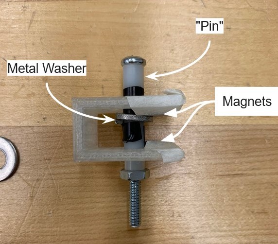
For the magnets, we experimented with a fridge magnet and neodymium magnets. We originally thought that neodymium magnets would be too strong, but once we found smaller magnets and built the pin prototype we realized they were the right choice for our mechanism.
Electrical
On the electrical side, we wanted to create a solid foundation for the rest of the project. To do this, we thought about using the servos to control cams, how to drive the cell chain, and general Arduino considerations and constraints.
We quickly wired a basic system to power one servo, with materials borrowed from the studio. This took no time at all, and allowed us to better visualize how the cams would actually move. This helped the team better understand how the different subsystems would interact.
We considered using either DC motors or stepper motors to drive the cell chain. After talking to course assistants, we decided to move forward with stepper motors. None of us had ever researched motors, so ordering one took a bit of time. This was complicated by not knowing how much holding torque we would need. Near the end of Sprint 1, we decided to purchase a NEMA 17 High Torque stepper motor with 42N.cm of torque.
We also discussed the limited storage space on the Arduino Uno and whether it would be a problem. After brainstorming, we decided to send instructions cell by cell (as opposed to all at once). This way, we knew we wouldn't have buffer overflow on the Arduino.
Software/Firmware
On the software/firmware side, our goal was to read a text file and convert that text file to braille 1 instructions to actuate a single cam system (one servo).
The program starts by reading a text file via Python's built-in file reader library. We chose not to create a GUI (graphical user interface) during Sprint 1 so we could prioritize working on Python/Arduino communication, our biggest software roadblock.
After it reads a text file, the program converts the text character-by-character to braille 1 mappings. While this worked for braille 1, we realized that later on in Sprint 2 that we would have to read things not character-by-character, but word-by-word to capture the contractions required in braille 2.
Last but not least, we send each character to the Arduino, which translates each braille mapping to a position on the servo. The largest challenge in Sprint 1 was communicating the braille 1 mappings to Arduino. We developed two protocols during this Sprint, one in Python for communicating/receiving from the Arduino, and one in the Arduino for communicating/receiving from Python.