Sprint 2
Goal: For Sprint 2, our goal was to have three cams and a chain of cells timed together to move pins to form braille characters.
Our goal for Sprint 2 was to create the cams, belt, and focus on getting the timing working together and moving pins to form braille characters. Sadly, we were not able to accomplish all of these tasks but we made a lot of progress & realized many potential barriers that we addressed for Sprint 3. We also learned a lot about our design through trying to achieve our over-scoped goal that helped us stay more in scope for Sprint 3.
Mechanical
Remote cam drive
At the beginning of Sprint 2, we were thinking ahead to how we could mount three servos to drive the cams without them clashing into each other. We wanted to get as close to 1:1 scaling of the spacing between real braille dots as possible, so space was at a premium. The way we mounted and drove the servos as well as the profile of the cams was important to design around as the small dimensions were very constraining.
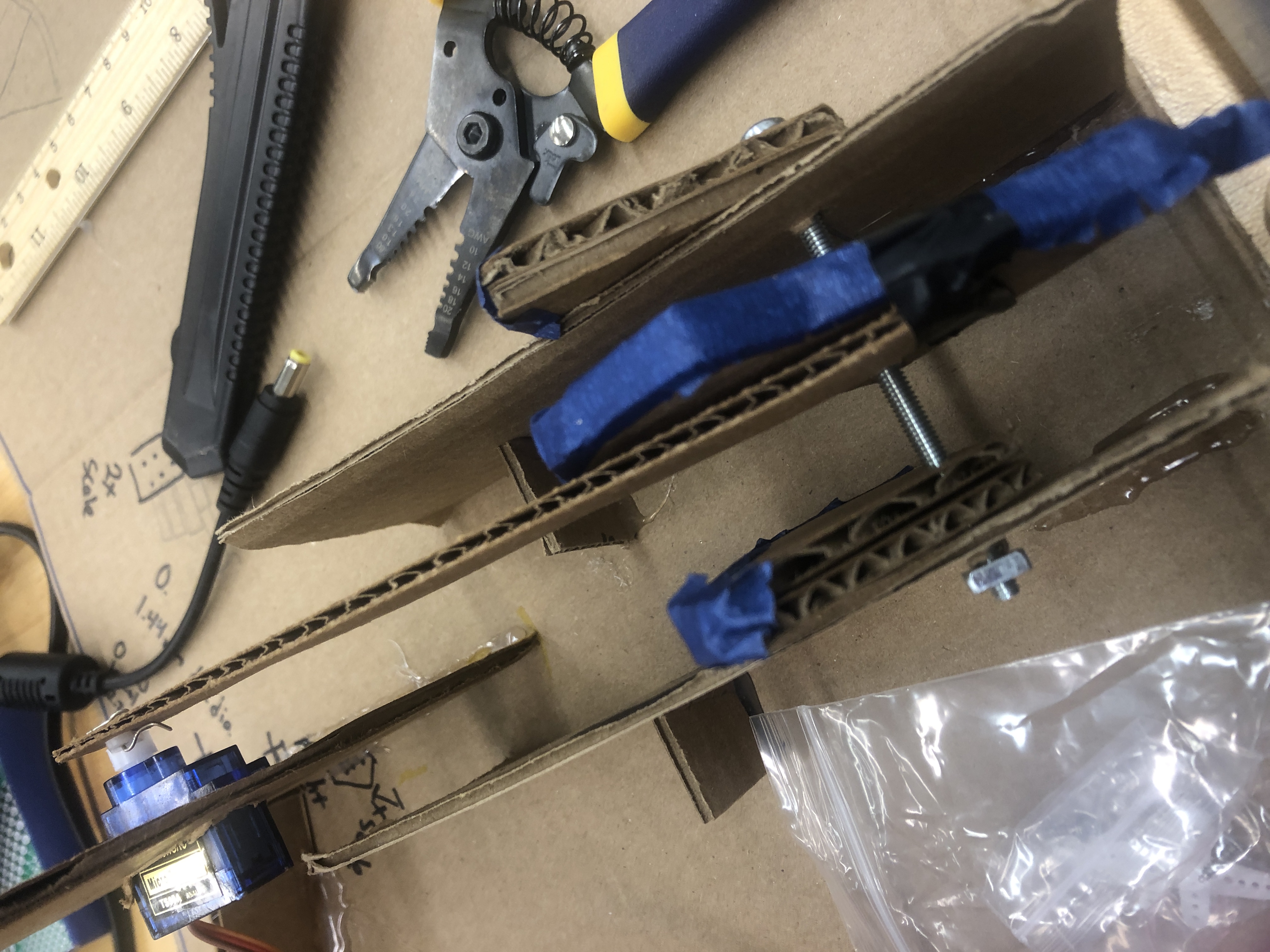
We built a cardboard prototype to verify that this four bar linkage design would work. This mechanism was not included in the integrated prototype that we showed during the Sprint 2 check-in. However, our cardboard prototype showed that this design was viable. We designed and CADed the remote cam drive linkages and they were ready to be fabricated at the beginning of Sprint 3.
Magnets
We experimented with several different types of magnets. We initially experimented with having a thin ceramic "fridge magnet" on the inside of the top and bottom of the cells with a magnetic collar on each pin that would snap to the top and bottom magnets. However, this was not viable as those kinds of magnets did not seem strong enough for our application. The other magnets we experimented with were small neodymium magnets; one kind was a very small 1/16" cube and the other kind was a small "donut" magnet. We did not fully consider how we were going to attach something magnetic to the pins and magnets to the cell, nor did we consider how we were going to attach a small magnet to each pin and a magnet surface to the cells in a way that was easily mass producible. We wanted to produce a relatively "large" number of cells, ideally over 20. Much of Sprint 2 was spent trying to figure out how to put an attachment on the dowel pins to make them properly magnetic to the magnets we had ordered. We did not manage to find a way to quickly and consistently attach either a magnetic surface or a magnet to the dowel pins.
Cells
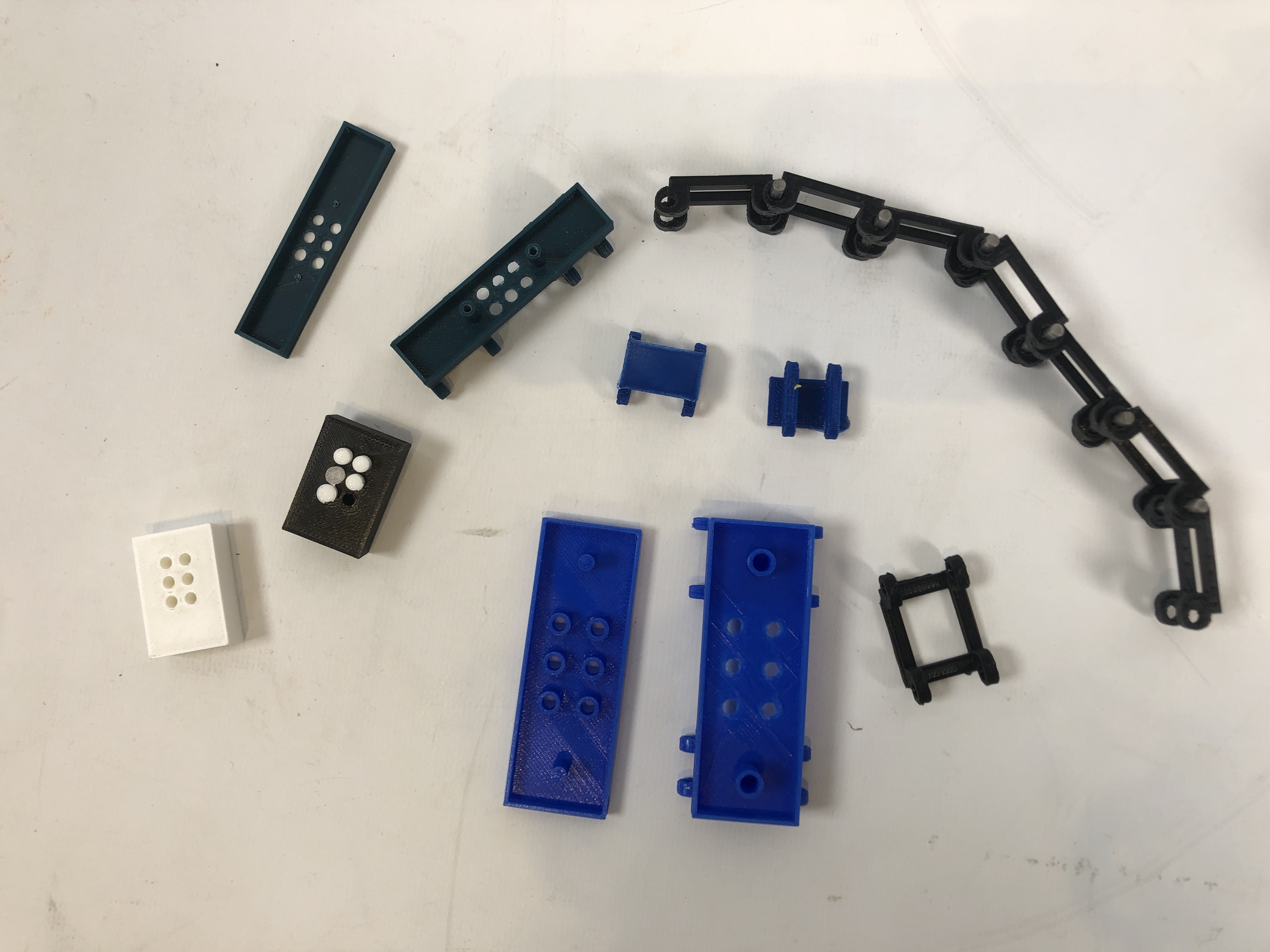
Given that each cell would be its owns piece that would be controlled the same way as every other cell, we decided to treat each cell as a link in a chain and connect them all that way. We iterated multiple times on the design of the cell, with the main design modifications happening around the size constraint mentioned in the remote cam drive section. As scaling increased, every dimension of the cell increased, except for the space of the sprocket slot, which remained the same.
Braille cell hole columns
We realized that if the pin in the hole moved in any other direction besides horizontally once it was below the surface of the cell, then it could wiggle out of place and be impossible to push back up. We added 'columns' to each cell hole to prevent this sliding. When we added these columns, they created square spaced pockets in between the holes. While we originally thought these square spaces could be used to hold the magnets that would hold the pins up, this idea was not effective and we could not figure out a way to easily get the pin to connect to the magnet.
Braille cell dimensions
We decided to scale everything up except the size of the holes and the pins. This means that we changed the spacing between each hole and between each character. At the beginning of this sprint, we were attempting to get as close to 1:1 scaling as possible, meaning actual standard braille size, so space was a big concern. Halfway through the sprint, we thought that 2:1 spacing was achievable and those were the space constraints we worked under. Through many design iterations and multiple 3D prints of our designs, we realized that even 2:1 scaling was too small. With the time and budget we had, laser cutting and 3D printing were the only real options we had for fabrication. This in addition to the quantity of cells and pins we had to produce, this meant that we did not have the time to build the cells and manipulate the pins at that scale. We ended up deciding to go with 4:1 scaling.
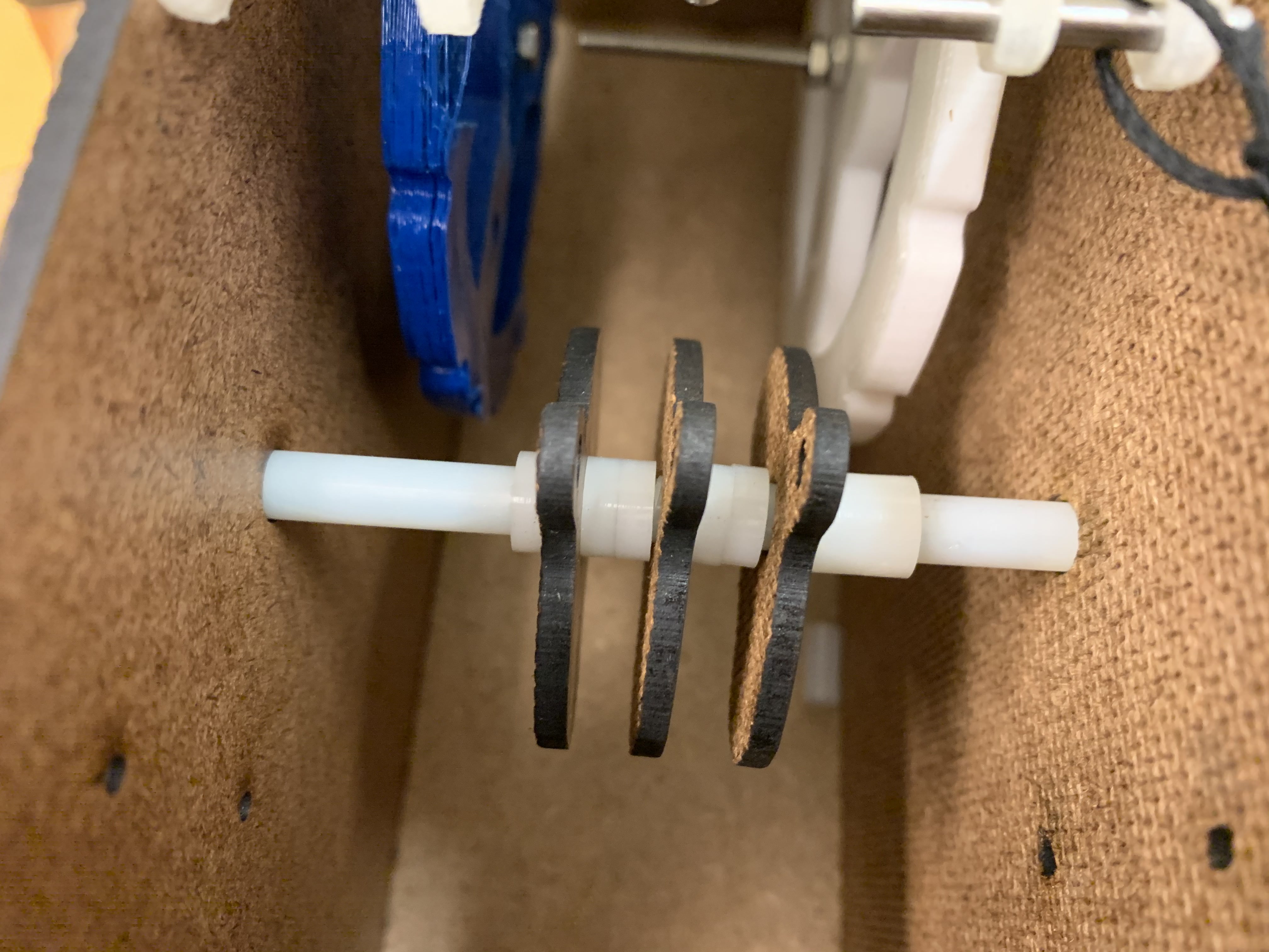
Chain
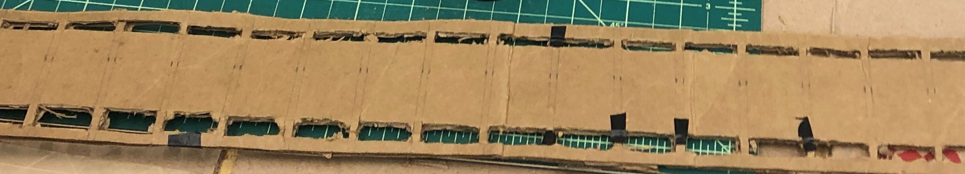
Even though we had decided on a final cell design to create the chain, we did not have enough time before our Sprint 2 check-in to print all the cells and assemble the chain. In order to have an integrated prototype for the deadline, we made a chain of cells out of cardboard. This functioned as a proof of concept for both the chain and the sprockets to drive it.
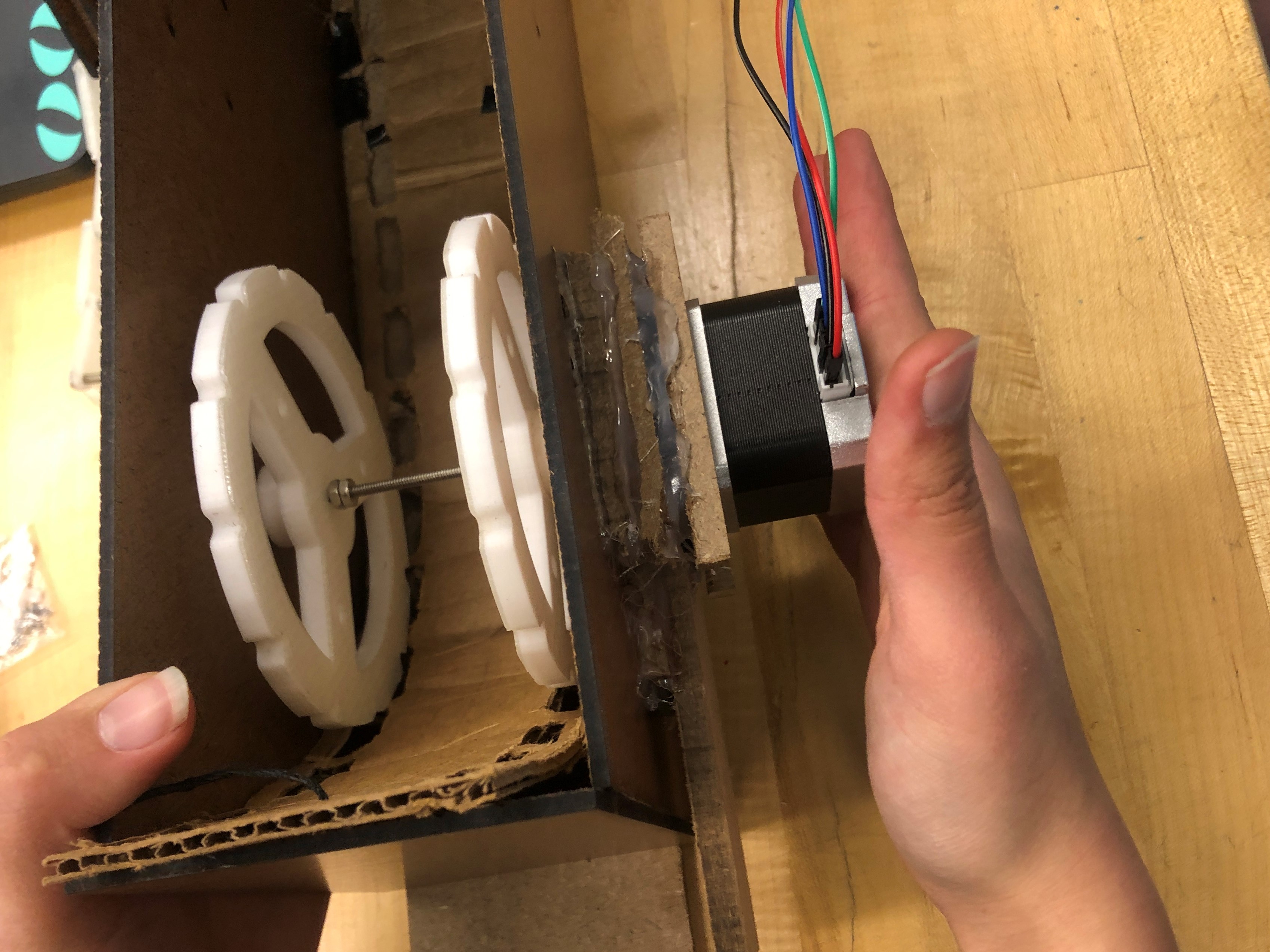
Sprockets
To drive the chain, we decided to use four identical 3D printed sprockets. We designed these around the size of the cells. With the original spacing, they originally were going to have 24 teeth, but when we increased the scaling, that number got halved to 12 teeth.
Pins
For our pins, we wanted to use an off-the-shelf part because of the number that we would need and how much that would cost. We decided to use dowel pins because they would move smoothly in the holes, came in short lengths that worked within our overall space constraints, and they were inexpensive.
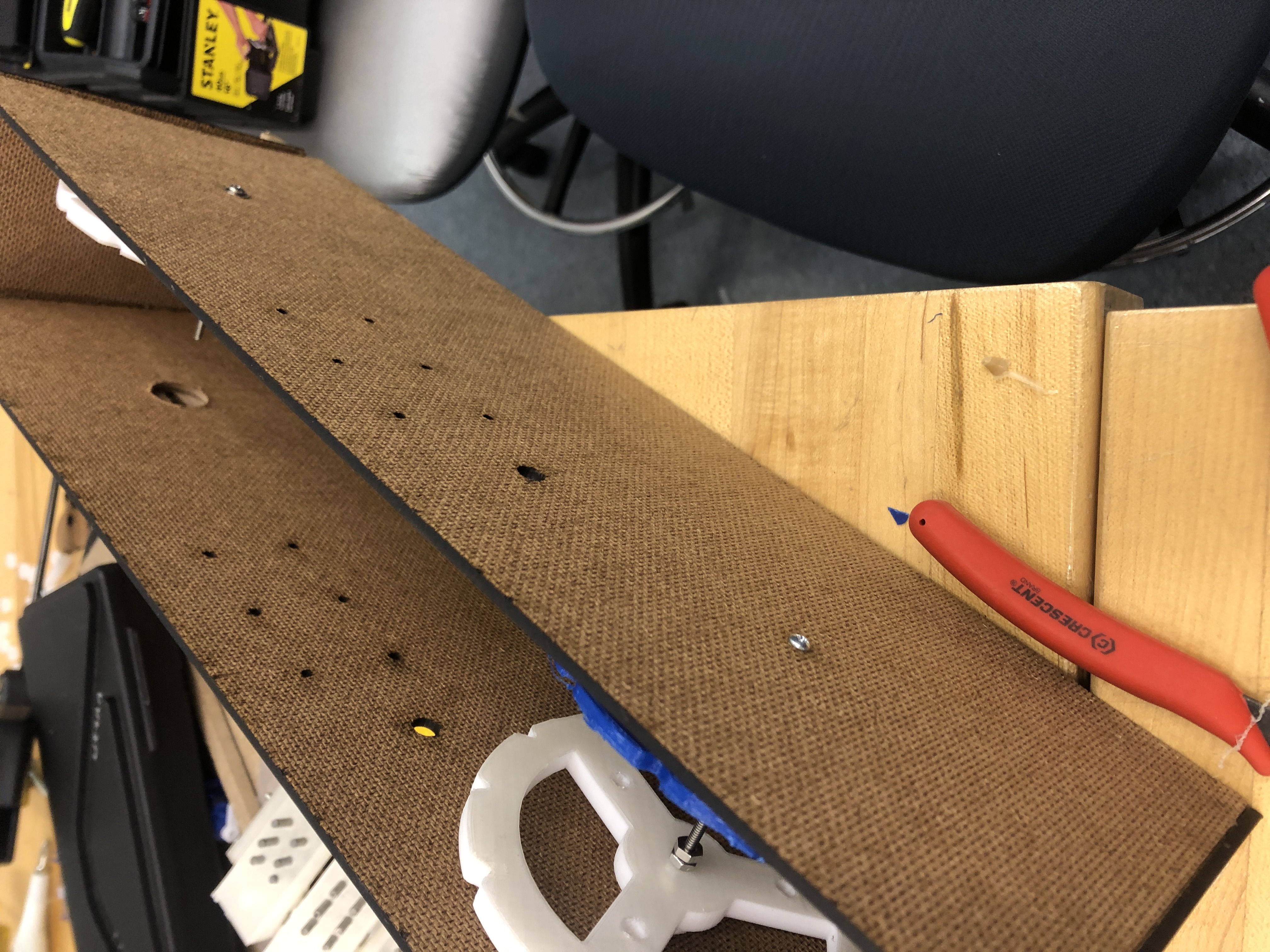
Housing
For the housing and how we would mount everything, we built a box built out of laser cut hardboard. At the end of this sprint, we had a housing with the sprockets and stepper motor mounted, but no servos or remote cam drive.
Cams
After the designing and testing we did during Sprint 1, we did not do much to change actual profile of the cams and how they would interact with the pins. The key feature that we worked on was how they would integrate with the remote drive linkages. Spacing and size constraints, a common theme throughout this sprint, was just as present here as it was in other parts of the system. We played around with a couple of different ideas for this interface such as a channel cut in the face of the cams and a linkage slightly less thick than that of of the cam so that if we attached the end of the linkage to the cam, the linkage with have space to move in that channel. The other approach was to have a tab that would come off the bottom and then a slot in the linkage into which the tab would go. At the end of the sprint, we had the cams mounted the integrated prototype, but they were not able to be controlled by the servos.
Reset mechanism
During this sprint, we thought about how we would reset the pins once they were set and after they were read by the user, keeping this part of the system on our radar during this sprint. However, this was not prioritized and so we worked on it only for the initial ideation.
Electrical
Our main electrical goal for Sprint 2 was to get the stepper motor working and finalize our servo selection. After some research, we ordered micro servos, as opposed to the larger servos used in Sprint 1. The smaller form factor allowed them to integrate easier within the mechanical system and rotate faster. The micro servos rotated 60 degrees with no load in 0.1 seconds with 4.8V, which allowed us to move the cam system faster.
After receiving our stepper motor and the motor driver, we thought it would be simple to integrate them with our circuit. However, after a lot of time triple checking our circuit, code, and talking to other students and course assistants, we came to the conclusion that we had received a package of bad controllers from Amazon. This set us back a few days. We were able to obtain another controller from Olin, but ended up breaking the potentiometer used to adjust the current limit. Luckily, a local hobbyist electronics store had some stepper motor drivers in stock, so we were able to obtain a working motor driver through them. This entire endeavor took about a week, but after a lot of circuit debugging and rummaging for parts, we successfully got our stepper motor to drive a chain of cells!
Software/Firmware
We made a lot of progress within our software and firmware! The largest milestones were: incorporating grade 2 braille, brainstorming and creating a skeleton for the control mechanism, creating a graphical user interface (GUI), and outlining a basic user experience workflow.
Grade 2 Braille
At the beginning of this sprint, we incorporated grade 2 into our system from a purely software perspective. Initially, we were going to create our own grade 2 conversion algorithm using a similar series of mappings like we had for grade 1. However, after further research and understanding of braille 2, we decided to leverage an existing library. While braille 2 does have contractions of both common words (such as "and", "for", and "the") and sounds (such as "ch" "sh" and "th"), it isn't as simple as direct mappings. The use of these shortenings depend on the sounds the letters make in that word, so they are not universally applicable. Because of that, translating to braille 2 is more difficult; in fact, only a human can ensure a perfect translation to braille 2. We used Pybrl which is an open-source grade-2 braille translation system written entirely in Python. Implementing Pybrl into our existing software was straightforward as we only had to make slight adjustments to our class.
Control Mechanism
As a team, we knew that we needed to figure out the timing of the chain with the cams as soon as possible, but recognized that we needed a physical prototype to test with in order to successfully figure out this component of the software. Since the fabrication of physical parts took longer than expected, we realized we weren't going to have the necessary physical system by the end of the sprint. Thus, the night before the sprint review, we decided to focus on creating a strong skeleton for the control, with constants as placeholders we could fill in later.
We thought of two directions we could pursue to control the system: we could continually move the cell chain and activate the cams at the correct times, or we could separate the steps into discrete, more hard-coded movements. Since there were still a lot of unknowns about the cam system and how the system would behave in the physical space, we decided to follow the second path. This way, we didn't have to worry about syncing the timing of the belt with the cams. The diagram shows our physical control mechanism for the mechanical components.
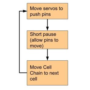
We created a skeleton Arduino code to achieve this goal. From there, all we had to do was measure the values for the number of steps and positions of the cams once we had all the mechanical components integrated.
Graphical User Interface
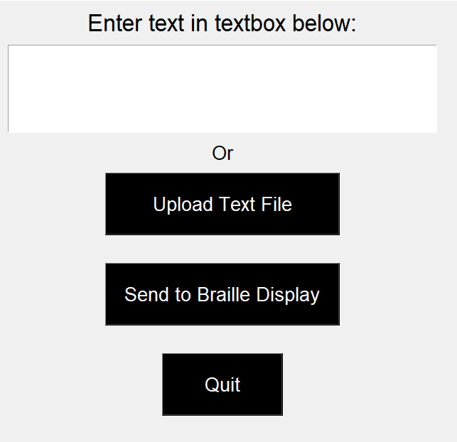
Before the Sprint 2 review, we created a GUI using the Tkinter library in Python. Since we wanted as many controls as possible to be physical, the GUI was designed to be minimalistic. The user can either enter text in a text box or upload a file to be read (which launches their operating system's default file explorer). From there, this text can be sent to the braille display. We were able to create the entire GUI in less than 30 minutes, which gave us more time to focus on getting our stepper motors to work.
User Experience Workflow
Although going through a co-designing process was out of scope for this project and our focus was on getting the system to work, we still wanted to devote some time to user interaction. At the end of Sprint 1, we talked to team members from the Fall 2019 Principles of Engineering Portabraille Printer team. They created a braille printer and also engaged in a deep co-design process with people who are blind or visually impaired. After talking to them about what they learned through their project and user research, we developed a basic user interaction process that would guide our decisions in Sprint 3.
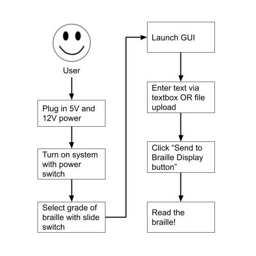
With these interactions, the beginning steps are physical, then switch to using the GUI, and then switch back to the system to actually read the braille. After ideating, this was the user flow we decided to stick with for our final system.