Sprint 3
In Sprint 3, we wanted to finish designing and fabricating all mechanical parts, finalize the timing of the chain (stepper motor) and cams (servo motors), assemble all parts to as close to the final version as possible in the time frame available.
Mechanical
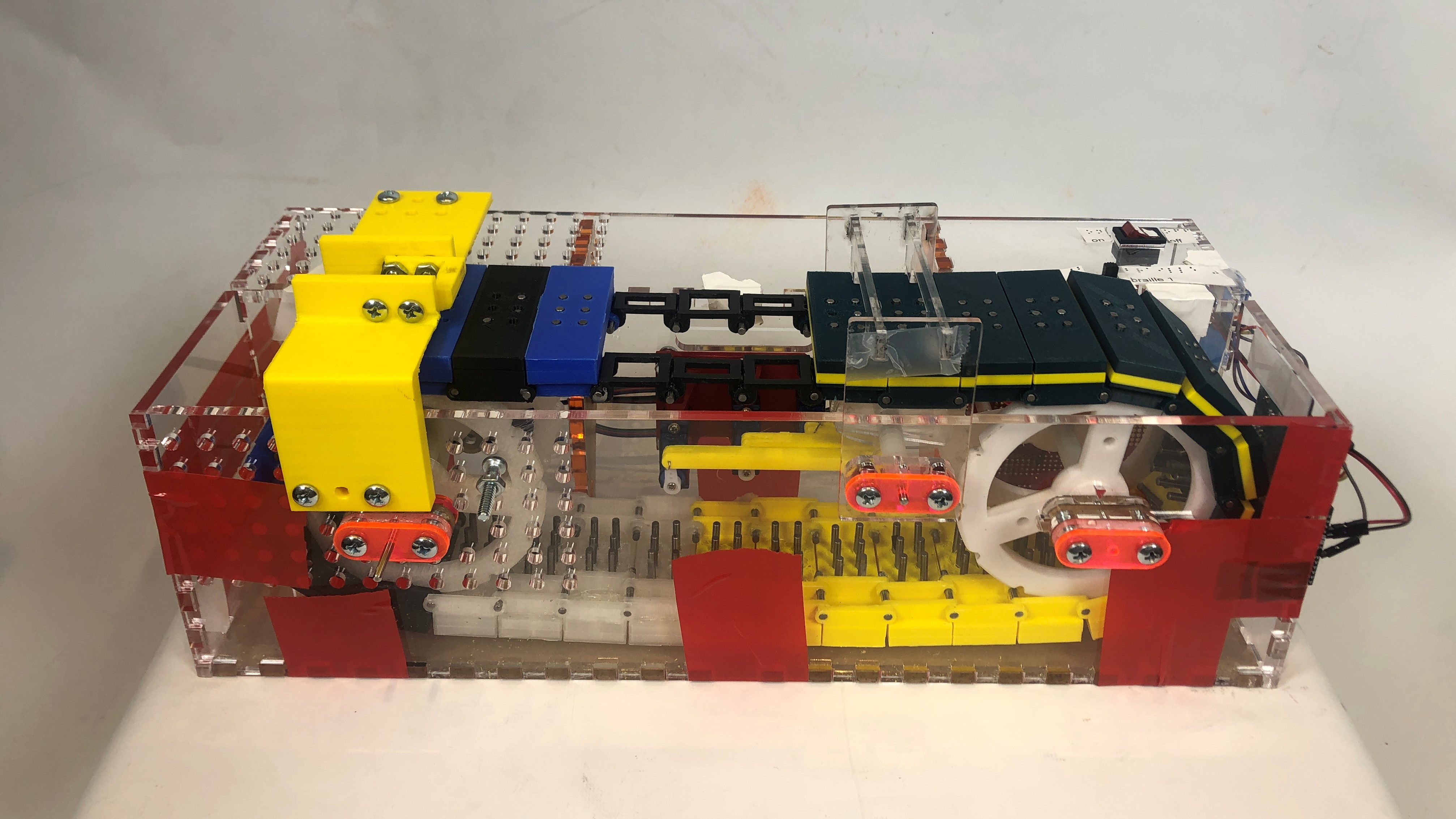
Cells
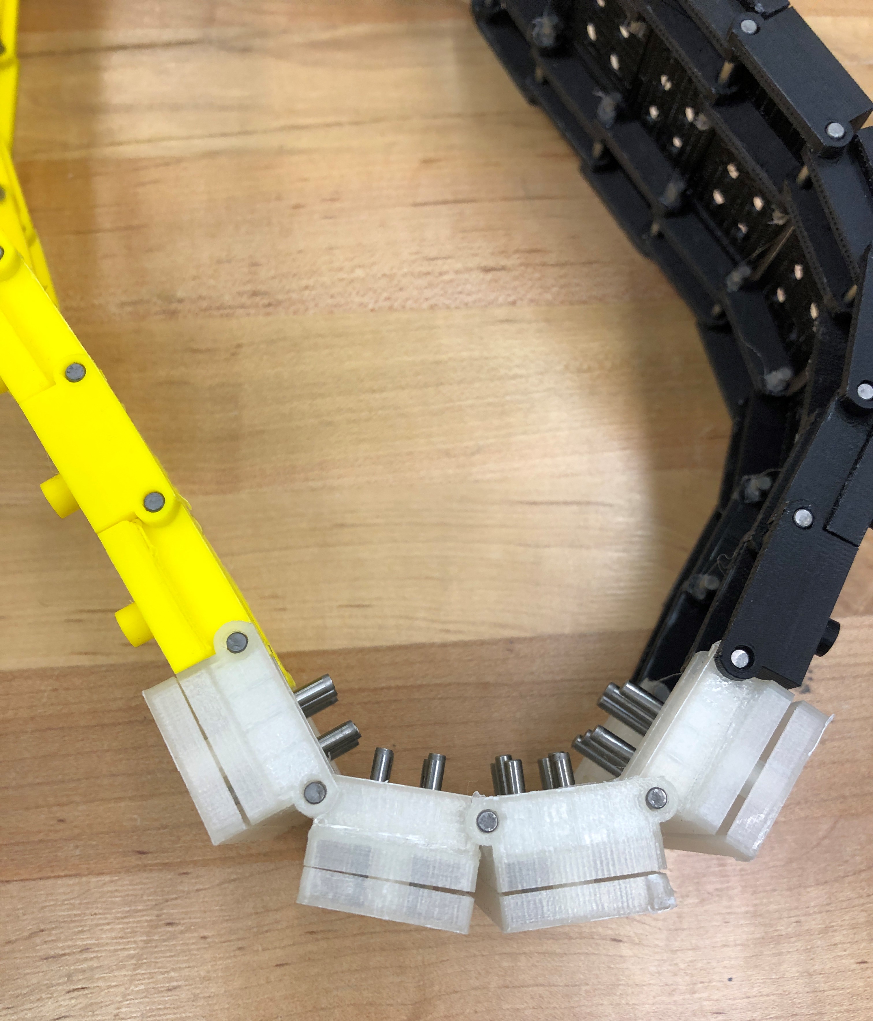
Since the cell design was finalized through many iterations in Sprint 2, all that was left to do in Sprint 3 was 3D print the cells to form the chain. We used 32 cells total, and formed the chain by connecting the cells with pins. Of those 32 cells, we had two types: a "live" cell and a "blank cell." A live cell was a full cell with all of the braille pins. A blank cell was made up of two separate pieces that would fill in the gap in the chain on both sides. We used a total of 28 live cells and 4 blank cells. The purpose of the blank cells was to allow us to more easily reach parts deeper in the housing.
Pins
Having tested the pins in sprint 2, we ordered more for the final version. When we put the pins in the cells, some fit the holes perfectly. Unfortunately, some of holes were too big and the pins were falling through the holes, or the holes were too small and the pins were difficult to press up or down. We suspect this inconsistency was a result of the 3D print tolerances. For the holes that were slightly too large, we put tape around the pin until it fit properly in the hole. We decided on this solution based on what we could do quickly in the time remaining in the project. For the holes that were slightly too small, we used a small circular file to remove some material and make the hole a bit larger.
Reset Mechanism
After the pins got set by the cams, we needed a way to set all of the pins back to a zero, or down, position. Otherwise, there would be a character limit that would be quickly reached before the user would have to manually push all of the pins back down, a tedious and time consuming operation. We wanted to do this as simply as possible, without having any sort of motor or servo required. To do this, we designed a wedge that would sit atop the chain. The tops of the pins would run into the wedge, driven by the belt, and get pushed down as they moved relative to the wedge. We 3D printed the wedge and its mounting brackets. We built the housing earlier in the sprint before the reset mechanism was designed and added in holes on the faces of the front and top panels to accommodate the reset mechanism and allow for adjustability. One mounting bracket attached to the front face and the other mounted to the ledge panel. The front face bracket mounted directly to the front face. The top panel bracket was designed to use spacers between the bracket and the top panel to reduce 3D printing time. Initially, the wedge did not line up exactly right with the pins. Spacers were added between the front face bracket and the front face to get the wedge lined up correctly.
Another challenge with this was properly setting the spacing between this and the surface of the cells. If it was too far away, then the pins would not get reset. It it was too close, than the friction between the reset and the top of the cell would be so great that the stepper motor could not overcome it. Initially, the reset was too close for all of the cells. We added spacers to move it slightly further away from the top of the chain. The issue we then ran into was that some pins were had super high friction and when the wedge hit the pins, the whole cell would be pushed down instead of just the pins. To help mitigate this, we first tried making little supports that sat on the walls of the housing and had ledges come out to support the bottom of the cell as they went under the reset. Ultimately, these did not work great. Instead, we moved where the reset mechanism was mounted so that it was mounted closer to the sprocket. This made it so that there was nowhere for the chain to flex as it was being supported by the sprocket. Now, instead of the chain getting pushed down, the pins would get pushed down as the resistance there was less than the resistance from the sprocket supporting the chain.
Remote Cam Drive
We 3D printed the remote cam drive that was designed in sprint 2. Since there are three cams in our design and we wanted to be able to drive them without them bumping into each other, we needed to offset the servo motors. This led to three linkages of different lengths. We wanted to keep the geometry of the driving linkages as simple as possible, give all three the same basic shape, and keep them from bumping. We mounted the servos in a line with their distance from the wall onto which they attached increasing with their distance from the cams. As we were securing the 3D printed remote cam drive parts to the servo motors, we realized that the holes at the attachment point on the servo side of the link were too large, and there was enough wiggling that the mechanism would not reliably move the cams as desired. We redesigned the attachment and reprinted the remote cam drive for the final assembly. On the cam end of the remote drive link, we attached the link and the cam using a 1/4" long dowel for each connection.

Sprockets
With the finalized design from Sprint 2, we 3D printed the remaining sprockets so they were ready to be assembled into the housing.
Axles, Bearings, & Spacers
For the sprockets and cams, we needed axles, bearings, and spacers. We bought these parts from McMaster. The axles were cut down to size after purchase. Each cam had its own bearing. The spacers were used to line up and keep the cams and sprockets positioned correctly.
Motor Mounts
We had two other critical parts that needed to be mounted to the housing. The first is the stepper motor. In the housing, there were holes for the axle, for bolts going directly into the stepper motor, and for additional bolts to aid the stepper mount. The bolts going directly into the stepper motor went through the housing, then stepper mount, and then into the stepper motor. To reduce the stress on these bolts supporting the stepper motor, we integrated a ledge for the stepper to rest on. Four additional bolts went through only the housing and then into the mount.
The other critical parts to mount to the housing were the servos driving the cams. Four holes were made in the housing to be used by the servo mount. As was mentioned in the "Remote Cam Drive" section, we mounted the servos in a line with their distance from the wall onto which they attached increasing with their distance from the cams. The servos all screwed directly into the mount and only the mount. The mount bolted to the inside of the housing and was one 3D printed piece.
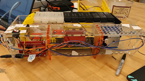
Housing
For Sprint 3, we wanted to improve the housing design by:
- Increasing the width of the box, since it was too narrow in sprint 2 and the cells were rubbing the inner walls and not moving smoothly.
- Changing the material from hardboard to clear acrylic so we could see inside and easily debug.
- Making the way the box fit together more securely than hot gluing the walls together (which is what we did in sprint 2).
- Using what we learned from sprint 2 about where to mount the motors and other components to put holes in the proper places on the walls.
We designed a new housing for the device components that incorporated these changes. The wall pieces have holes to mount the servo motors, stepper motor, reset mechanism, Arduino, and protoboard, as well as a place for a barrel jack (on the side of the housing to easily connect to power). Since the reset mechanism was not completed when we laser cut the housing, we added grids of mounting holes on the front and top faces so we could have the flexibility to mount the reset mechanism at various locations later on. This allowed us to move forward with assembling the rest of the system, and we integrated the reset mechanism a few days later. The panels were designed with finger joints on their edges so we could easily assemble the housing. Finger joints also ensure that the design will be rigid and self-aligning.
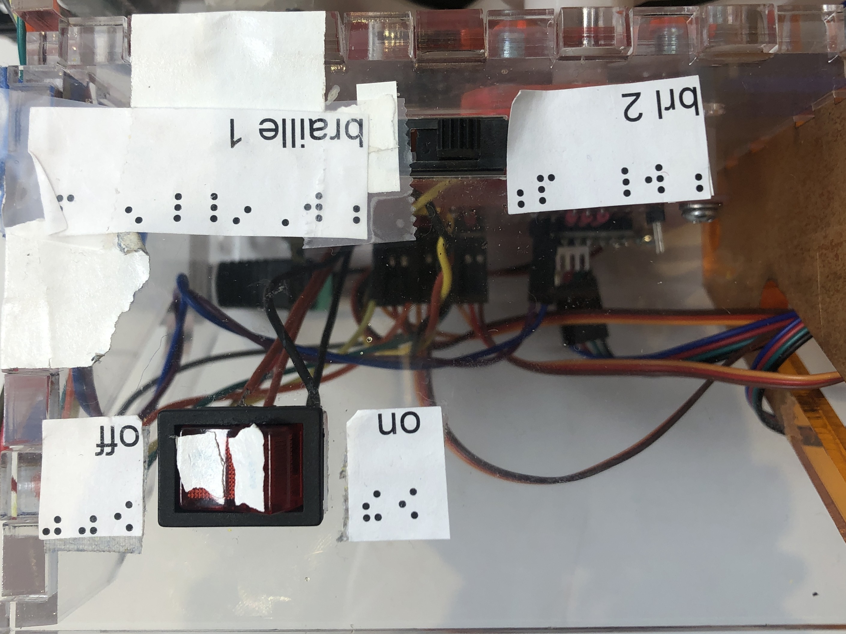
Another component of the new housing design was the ledge for mounting switches for the user to turn the display on/off and control which type of braille it would print. We chose to put these on the side of the device that is further from the person reading to keep them out of the way. Since the ledge was connected to the top surface of the front wall, we also designed and cut two triangular supports to hold it up. These supports had wire routing holes to keep the wires in place.
We decided to fabricate the housing using clear 1/4" thick acrylic so we could see how our components were moving for easier debugging. Clear acrylic was also available on campus (at the Foundry). We included slots where one set of sprockets attached so that we could adjust the tension of the chain.
Once the housing was assembled and all components were inside, we realized that, despite tensioning the chain, the contact between the pins and the cam was pushing the entire cell up instead of only the pins. We designed an attachment over the top of the housing on the opposite side of the reset mechanism that holds the cell down.
Cell Ceiling
This was happening because the friction fits of a portion of the pins were too tight. To help mitigate this, we designed an attachment to be a "cell ceiling." This part functions as a bracket that went over the top of the cells above the cams. When the cams were actuated, if there was resistance from the pins and the cell got pushed up, the top of the cell would hit this "ceiling" and the path of least resistance would go back to being moving the pin rather than the chain. We learned from our struggles with the reset mechanism and designed adjustability into the mounting brackets for this piece. Instead of going through holes, the bolts went into slots before getting tightened down. In our first version of this piece, the edges of the cells would get caught on the ceiling as the chain would move. Since the ceiling was made up of 2 separate pieces, the chain would jam. To prevent this issue, we filed down the parts that were directly in contact with the tops of the cells and adjusted the distance from the cell ceiling to the cell.
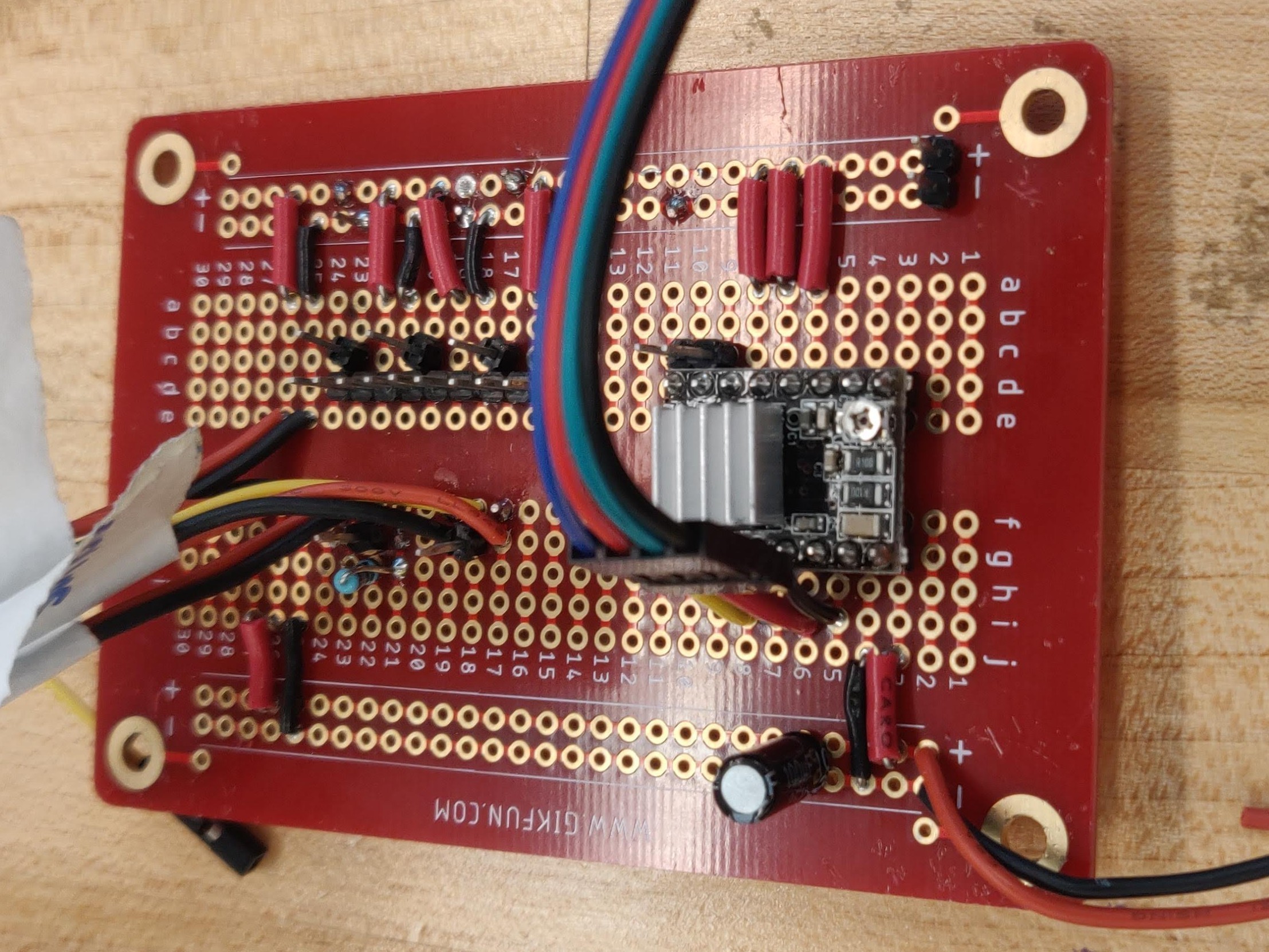
Electrical
In Sprint 3, we made a few improvements to our circuit and user interaction and then transferred the circuit to a solder-able protoboard. To power on and off the system and both power sources, we use a double pole single throw (DPST) switch. This allows us to easily turn on and off both power rails (the 5V for the Arduino and the 12V for the stepper motor). We also added a slide switch to control the grade of braille. The final circuit and the physical controls are shown below.
Software/Firmware
During Sprint 3, we refined our driver code and calibrated the cam/stepper motor system. As we designed our control mechanism at the end of Sprint 3 and built a skeleton, all we had to do was determine constant values. We measured the number of microsteps to move from one cell to the next. We also determined the positions for the servos to actuate the pins. This was a lot of trial and error, as each servo needed slightly different values to activate the pins. After this, we had a fully integrated system that was able to create braille cells!
Timing
Instead of having cell chain move continuously and coordinating the cams to activate the pins while the chain was moving, we decided to instead sequence these actions.
- Belt moves to align the cell with the cam
- Cams move to the right position to actuate the pins included in the current braille letter being printed
- Once the pins have been pushed up, the belt moves again to move to the next cell
- Repeat
GUI
The GUI was completed in Sprint 2.
Switches
We integrated the braille 1 and braille 2 switch code with the Arduino.