
Electrical Overview
The electrical system consists of the power distribution system, as well as the sensor wiring on both the chassis and the tray module.
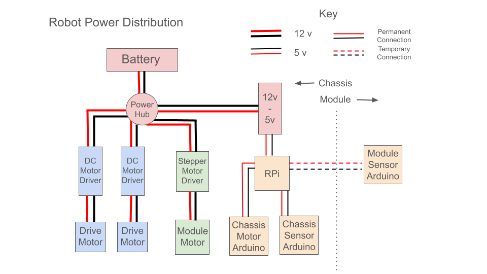
Power Distribution:
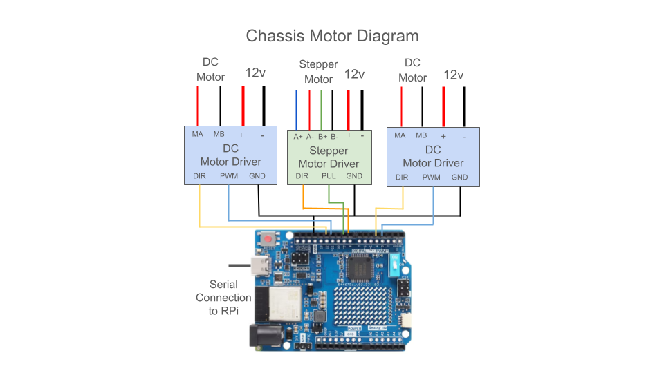
The robot is powered by a 12v 3000mAh battery, which is distributed to two 12v DC drivetrain motors, a stepper motor for the module, and a Raspberry Pi through a buck converter. The Raspberry Pi in turn powers all three Arduino UNOs over USB. Both drivetrain motors are controlled using PWM signals from an Arduino and a 13A motor driver. The stepper motor is controlled by an Arduino through a stepper motor driver.
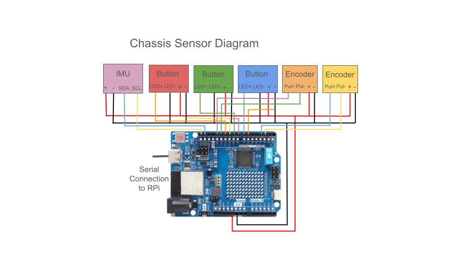
Chassis Sensors:
On the chassis we had three buttons, two motor encoders, and an inertial measurement unit (IMU). All these sensors are powered by an Arduino Uno. The buttons and their integrated LEDs are wired to digital pins so they can be controlled and read. The encoders are wired to interrupt pins so the firmware can detect when there is a change in voltage. The IMU is wired to the SCL and SDA pins on the Arduino, and is mounted at the center of rotation of the chassis.
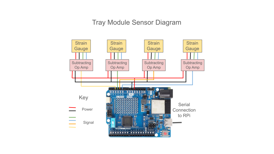
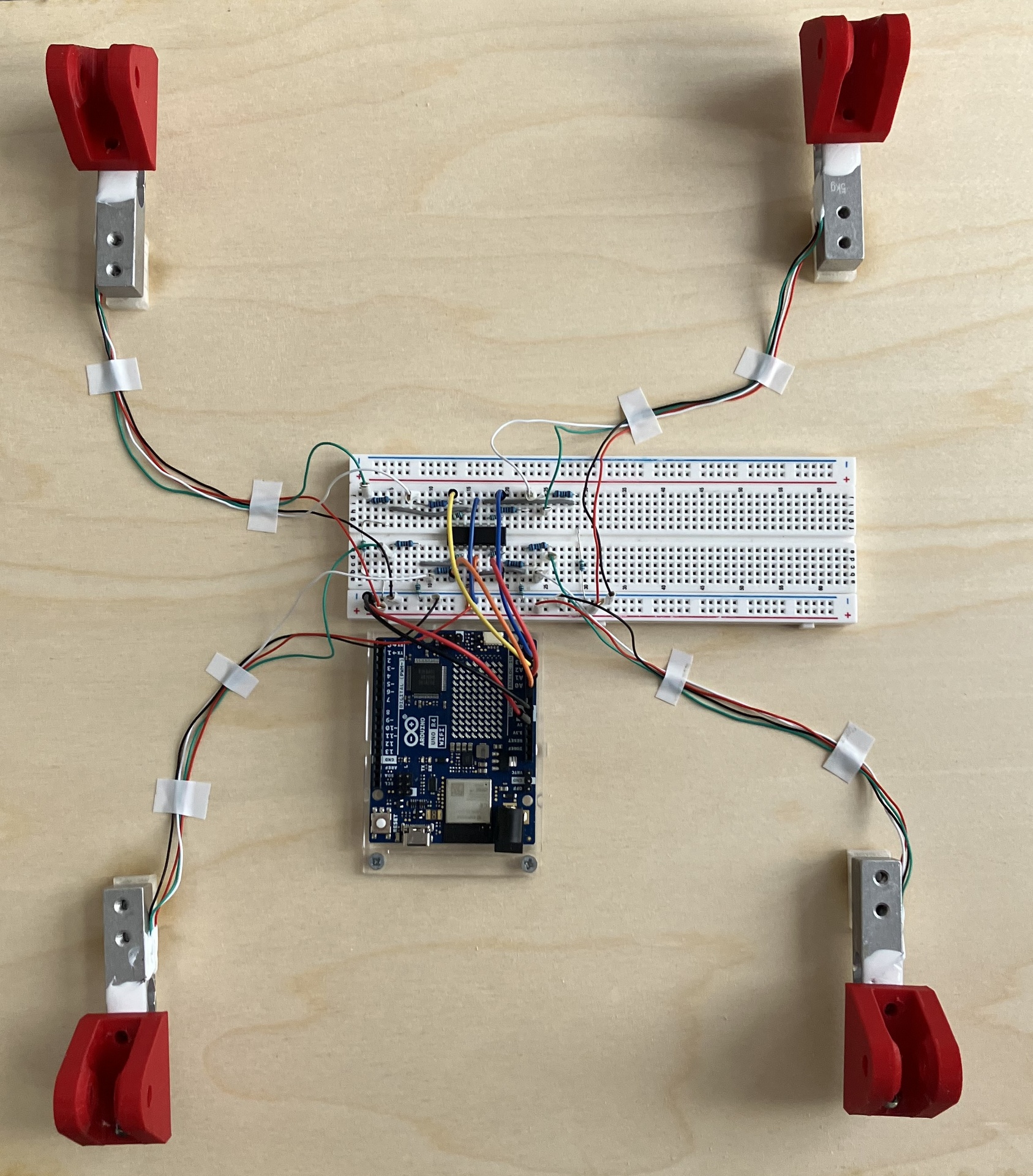
Tray Module Sensors:
On the tray module, we have four strain gauges, which are powered by a separate Arduino Uno. They are each the variable resistor in a wheatstone bridge which is amplified by an operational amplifier (OpAmp) with a gain of 1000 before being wired to analog inputs on the Arduino.
This site was created with the Nicepage