
Firmware Overview
Our firmware lives on three Arduino Uno microcontrollers that interface between the hardware (motors and sensors) and the Raspberry Pi. We initially wanted to use microROS on Raspberry Pi Picos to communicate with the software system using ROS protocol. With such an ambitious project we decided to pivot to Arduino Unos and communicate over serial. We decided to have different Arduinos for receiving motor commands and passing along sensor data to simplify serial communication. For sensors without specific open source libraries such as the buttons, encoders, and strain gauges, we wrote our own custom libraries.
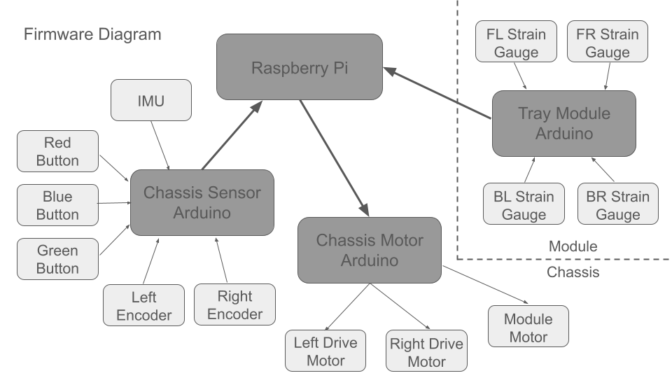
Motor Firmware:
The Arduino receives serial messages from the Raspberry Pi and parses them to determine if they are meant for the drivetrain motors or the module motor. Once it has done so, it processes the rest of the message; either a twist (linear and angular velocity) for the drivetrain, or angle for the module motor. For the drivetrain, we calculate the left and right wheel velocities, and using an open source library, send PWM signals to the motor drivers. If it is a command for the module motor, we calculate the number of steps the stepper motor needs to move, and use an open source library to send the stepper motor to the specified angle.
Chassis Sensor Firmware:
The Arduino on the body of the robot processes and relays data from the buttons, encoders, and IMU to the Raspberry Pi. With each message it identifies what sensor the data originated from using a two character code. The firmware for the buttons is a library containing a button class and two methods which initialize the button, and check if it has changed states. The encoder firmware reads two channels, which are identical square waves offset by 90 degrees, where the number of pulses is the speed, and which channel is ahead of the other is the direction of rotation. The encoder firmware library has a robot class with three methods. The methods each initialize the robot with both encoders, return linear velocity, and return angular velocity respectively. The IMU had an open source firmware library already written which we leveraged to get linear and angular acceleration readings.
Tray Module:
The tray module firmware consists of managing four strain gauges to determine if a plate has been removed or placed while the tray is extended. We wrote a custom library for the strain gauges as well, which includes a tray class and two methods. The first method initializes the tray with all four strain gauges, and the second checks if a plate has been added or removed by checking to see if the state of the tray has changed in the correct order as the tray has extended and a plate has been added or removed.
This site was created with the Nicepage