
Software Overview
Walter's software system runs entirely using ROS2, a robotics middleware tool that allows us to abstract our robot’s software into a network of independent tasks called “nodes”. We created the following system diagram to explain how Walter’s ROS2 nodes pass information, perform calculations, and then act upon the world autonomously:
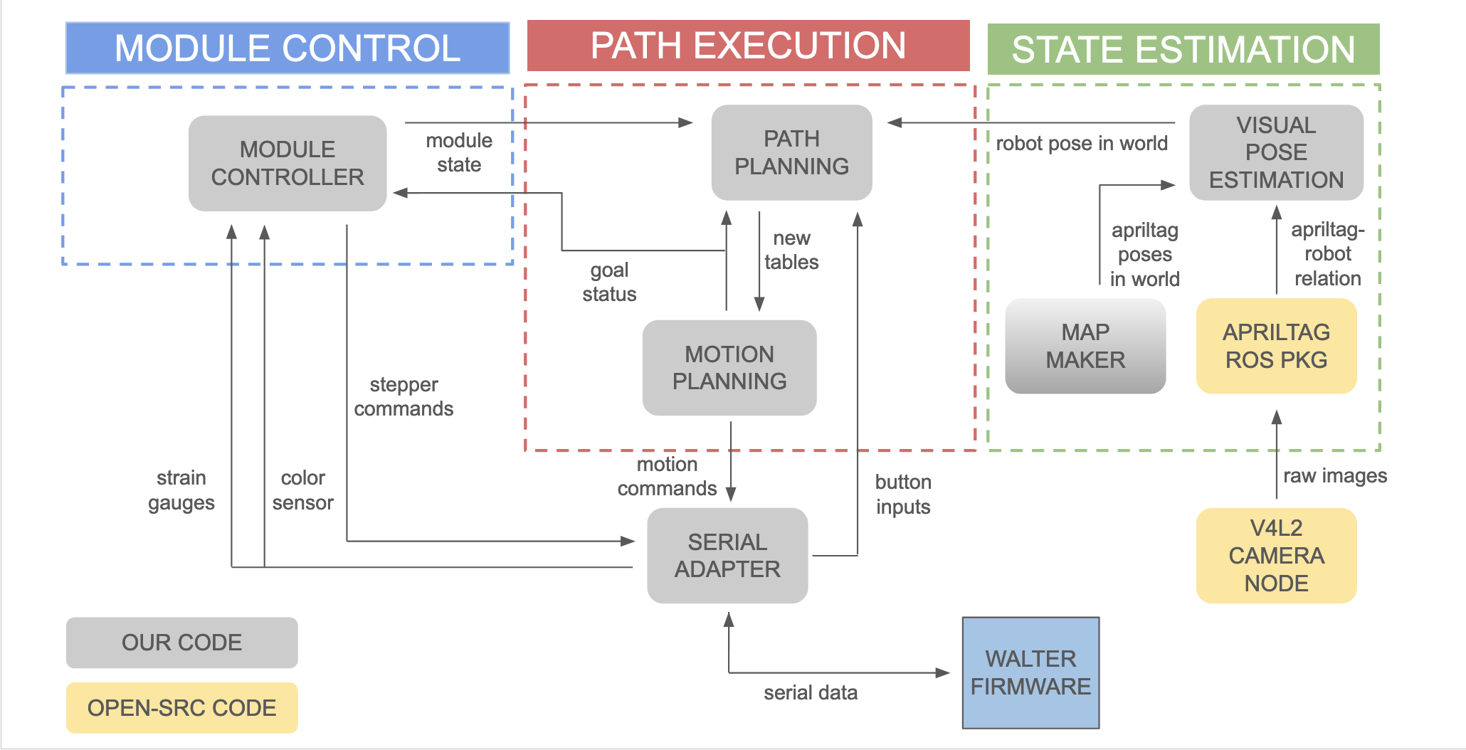
The robot’s software has three main system components: state estimation and localization, path planning and execution, and module control. Critical information such as its current position in the world, or its current destination, are passed between the nodes and used to make decisions. This is a completely autonomous system in which the only human input comes from pressing buttons to request a “delivery” to a certain destination.
State Estimation and Localization:
For this project, we want Walter to be able to localize where he is in the world frame regardless of where he is. The approach that we chose was to use computer vision to detect apriltags, and through frame transformations, return a pose estimate of where Walter is within the world. Our first step is to calibrate our camera. To do this, we will need the following things: a camera ROS node that publishes images, a camera calibration ROS node, and a 7x9 white calibration paper.
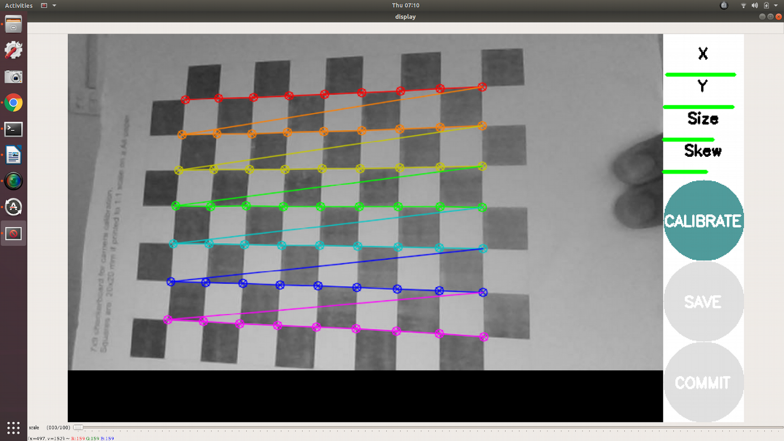
Once we are done, we save the calibration file in ~/.ros/camera_info/[camera_name].yaml so that it could be accessed by the camera node in the future.
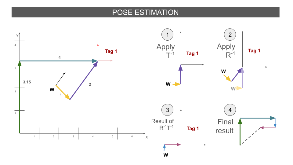
Once this is complete, we set up the Apriltag ROS node developed by Christian Rauch. Fortunately for us, the Apriltag ROS node publishes transformations to the /tf topic. In this topic, we will get information about where the apriltag is with regards to the camera frame. We simply take the inverse of the transformation provided TR, where R is the rotation matrix and T is the translation matrix. This will result in the matrix R-1T-1. Finally, we apply the transformation between the world frame and the Apriltag to give us our final result. We publish the result as a Pose object.
Path Planning and Execution:
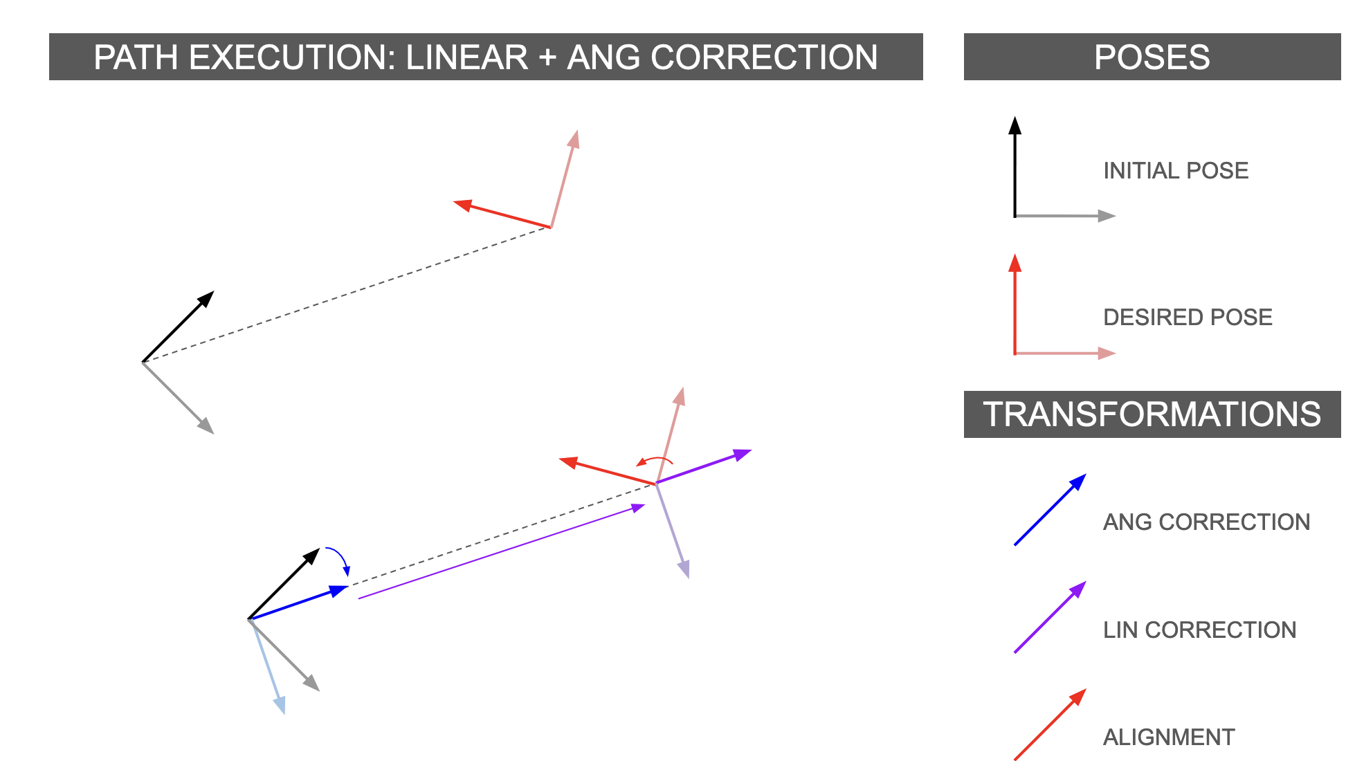
Walter’s path planning system includes a map maker, a path planner, and a motion execution node, which work together to ensure Walter efficiently gets to where he needs to go. The map maker manages his reference map of the world, including AprilTag landmarks and table coordinates, using the ROS2 TransformManager tool. When a person presses a button to indicate where Walter should go next, the motion execution node uses this reference map along with a recent estimate of Walter’s location to figure out the velocities necessary to get him there quickly. This diagram showcases how Walter prioritizes correcting angular error over linear error to get to his destination:
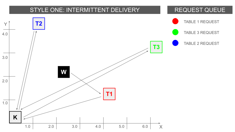
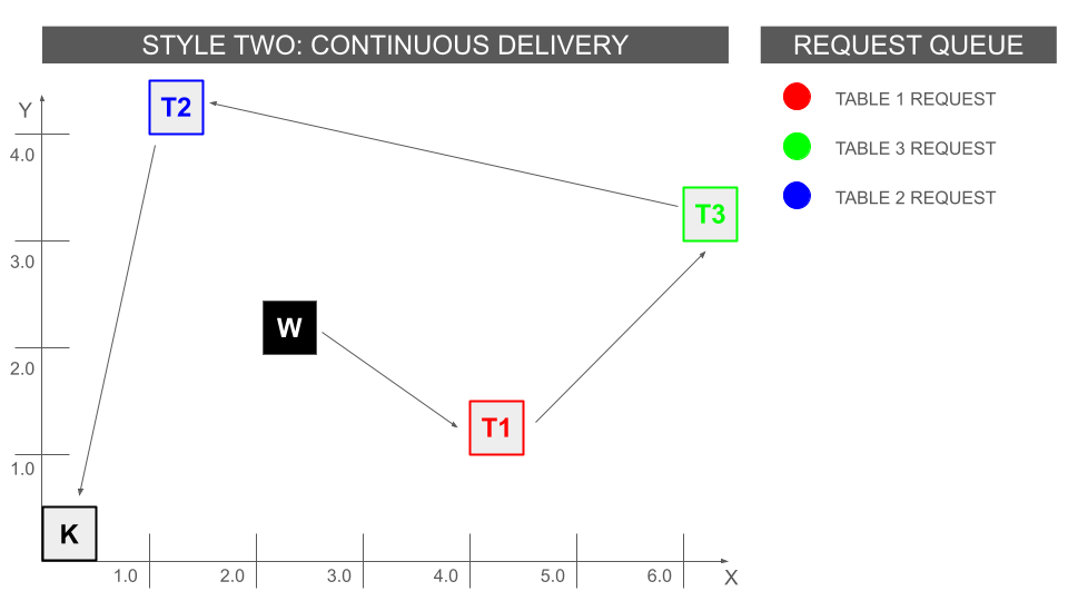
If Walter receives multiple destination requests, the path planner files them into a queue and only allows the most recent request to be visible to the rest of the system – this avoids routing interruptions and keeps Walter’s path stable. The path planner can be configured to either send Walter from one destination to the next, or to require him to return to the kitchen each time he completes a delivery. The two modes are visualized below:
Module Control and Serial Data:
The module control node is in charge of controlling when to extend and retract the four-bar module. When Walter reaches a new destination, module control node actuates the four-bar to offer food. When someone removes weight from the four-bar, the strain gauges underneath communicate this to the model control node and it commands the four-bar to retract. When the four-bar is completely retracted, the node will indicate to the path planner that Walter is ready to pilot to his next goal.
An important aspect of this control is its ability to track its status. We split the system into four following statuses.
0. Walter hasn’t reached its destination
1. Extend the arm
2. Retract the arm
3
. Waiting for next goal location
By doing this, we can specifically tell Walter that it shouldn’t move when the four-bar module status is at 1 and 2. Furthermore, we can publicly publish to all other nodes so that other nodes will know to set the next location when the four-bar module status is at 3.
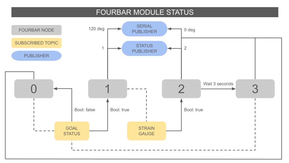
To communicate with our Arduinos, we created a serial ROS node that either parses data coming from the read port or strain gauge port and sends data to the write port. The table below shows the codes we used to make sure our firmware and software are properly integrated.

External software dependencies:
Pip requirements:
ament_copyright==0.12.11
ament_flake8==0.12.11
ament_index_python==1.4.0
ament_pep257==0.12.11
apriltag_msgs==2.0.1
geometry_msgs==4.2.4
launch_ros==0.19.7
numpy==1.21.5
opencv_contrib_python==4.10.0.84
opencv_python==4.10.0.84
opencv_python_headless==4.8.1.78
pyserial==3.5
pytest==6.2.5
rclpy==3.3.14
setuptools==59.6.0
std_msgs==4.2.4
tf2_msgs==0.25.8
tf2_ros_py==0.25.8
tf_transformations==1.1.0
External ROS nodes
v4l2: https://github.com/tier4/ros2_v4l2_camera
apriltag_ros: https://github.com/christianrauch/apriltag_ros
camera_calibration: https://github.com/ros-perception/image_pipeline
Github
https://github.com/itannermahncke/pie_waiterbot
This site was created with the Nicepage