
Mechanical Overview
There are three distinct mechanical systems of the robot: the drivetrain, module interface system, and tray module. This diagram explains the flow of energy in our mechanical system:
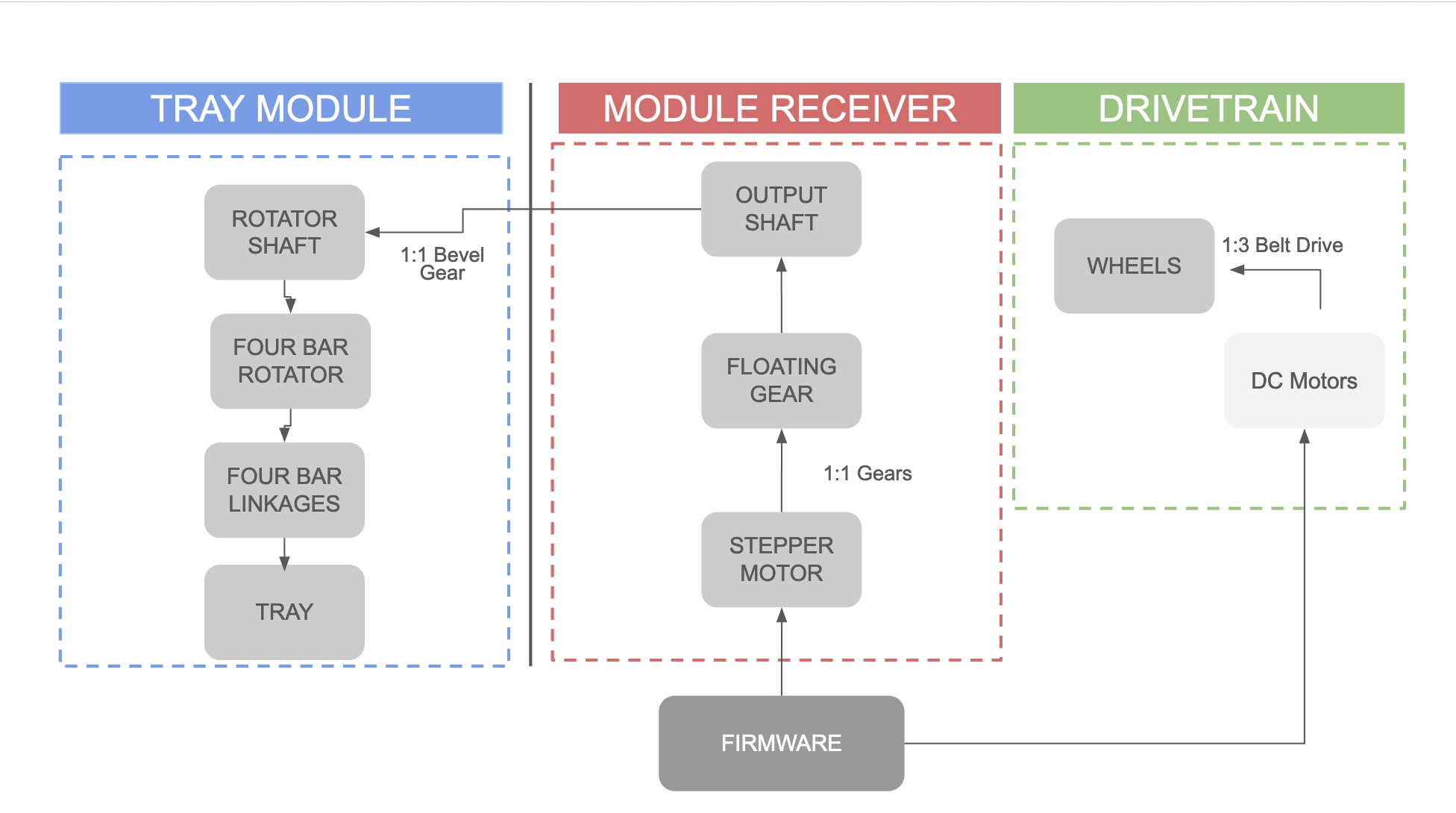
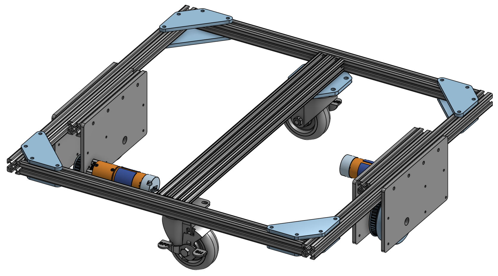
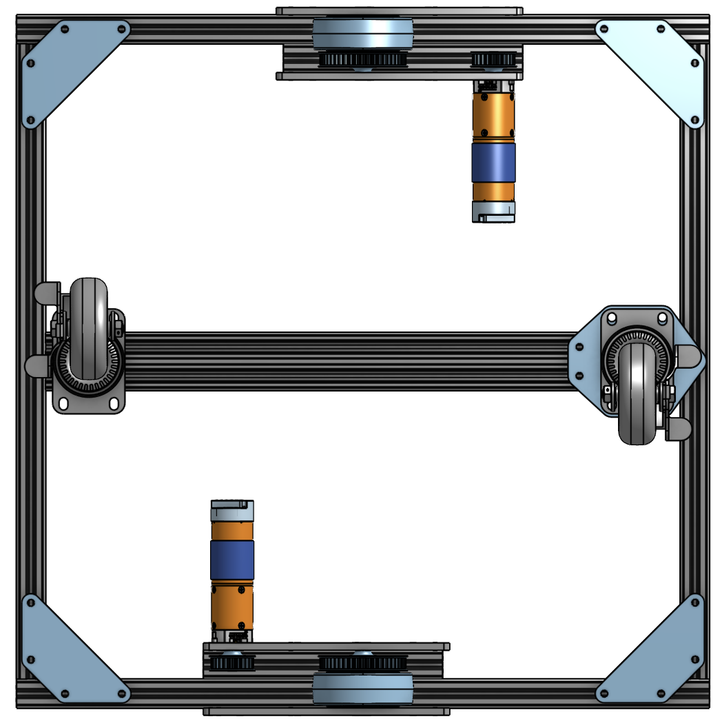
Drivetrain:
Our robot’s drivetrain consists of two centered drive wheels mounted to a 2ft x 2ft chassis made out of 1010 aluminum extrusion. Two caster wheels are mounted to either side to stabilize the chassis while still allowing the robot to be driven with only two powered wheels. The powered wheels are each connected to a DC motor through a belt system with a 2:1 gear ratio.
Module Interfacing System:
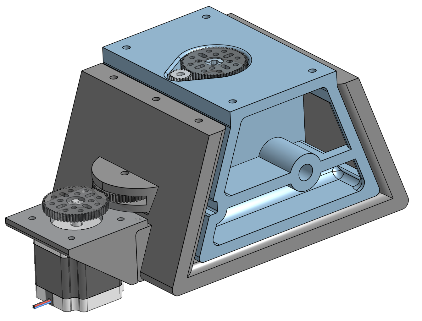
Our robot uses a modular interfacing system to allow for seamless switching between different modules, including our serving tray module and other potential features. We use a module housing unit mounted to the top frame of our robot. The module housing is 3D-printed with ABS, and uses a stepper motor connected to a series of gears, the end of which protrudes into the interior of the housing.
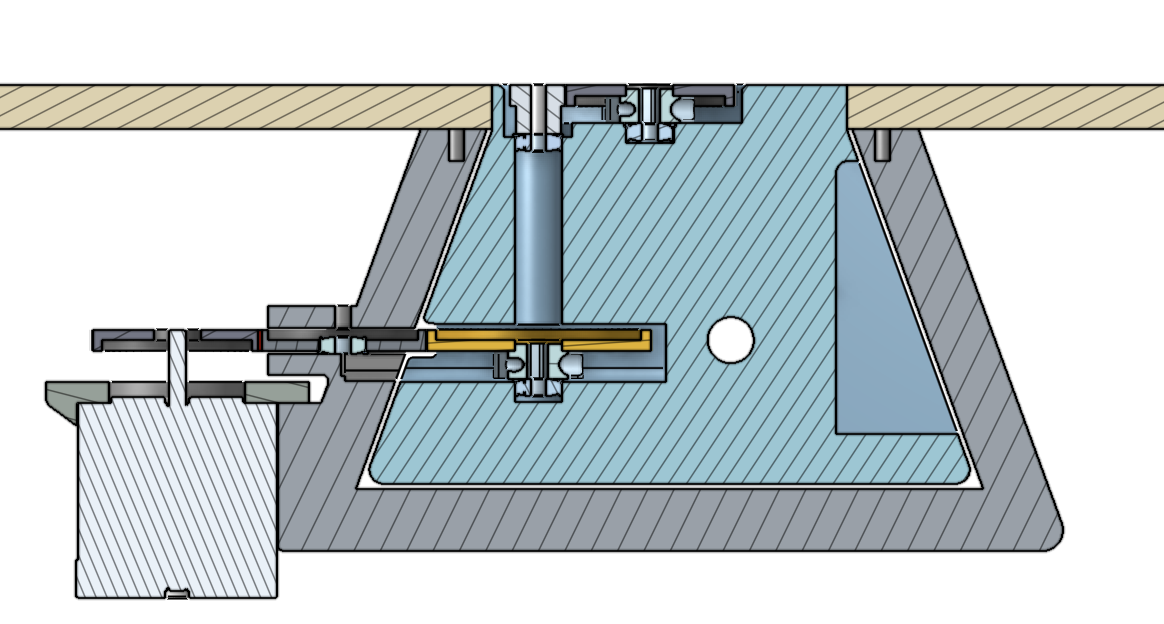
Each module contains a module receiver, another 3D printed piece designed to interlock with the module housing. To insert a module, the receiver can be easily slid into the housing, which allows the gear on the receiver to mesh with the gear on the housing, allowing for the transfer of rotational energy. A key on the receiver can then be turned to lock the module into place. When the stepper motor is actuated, the gears will transfer rotational energy between the housing and the receiver, and into a vertical shaft in the receiver, which the module can then use.
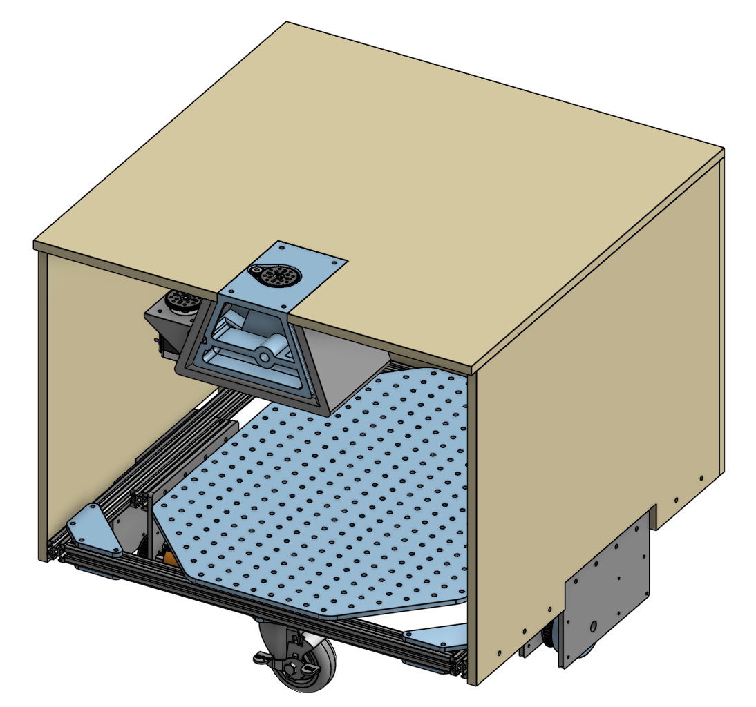
This is a cross-sectional view of the module receiver secured in the module housing:
Tray Module:
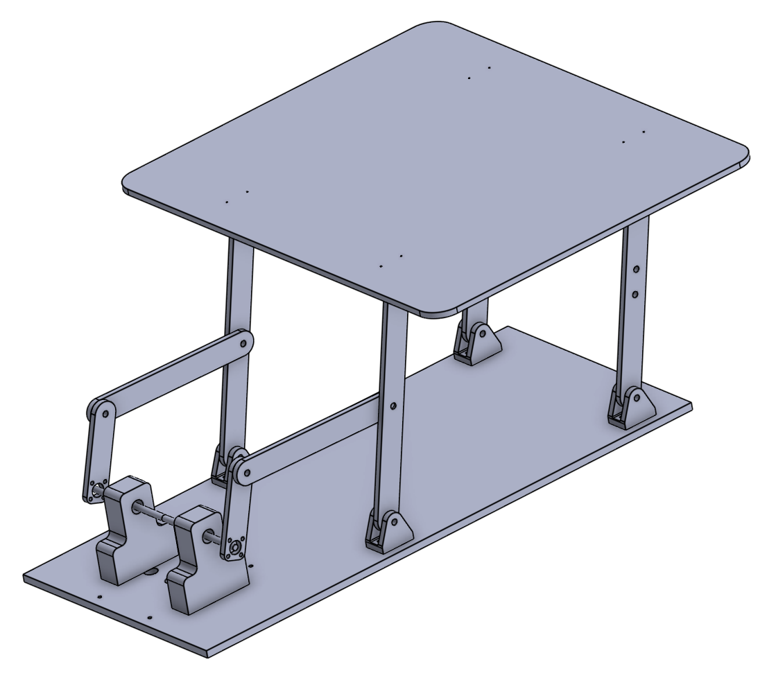
The tray module uses a four-bar linkage to extend the tray outward, which customers can then pick up dishes off of.
When the stepper motor rotates, the vertical shaft from the module receiver interfaces with a horizontal shaft via a pair bevel gears. This horizontal shaft powers the four-bar mechanism, by rotating a crank connected to the linkages. The linkages are made from laser-cut acrylic, and attached to the bottom board and the tray through 3D-printed brackets that act as pin joints, allowing the links to rotate but otherwise lock them in place.
We also installed strain gauges between the linkages and the bottom of the tray, and wired them to a central arduino, so we could detect when a dish had been removed from the tray.
This site was created with the Nicepage