Firmware is where everything comes together
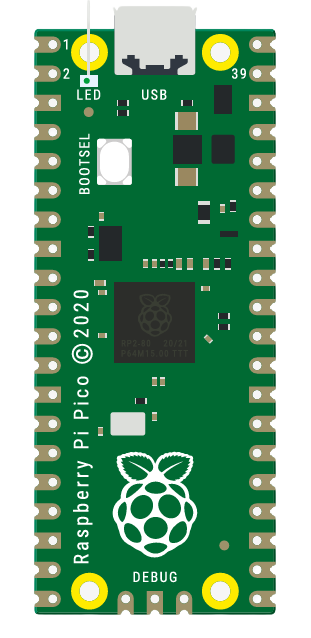
The Raspberry Pi Pico is the heart of our system. This very small 21x51mm form factor RP2040 had barely enough power to handle our entire system. The RP2040 has a dual-core design, which we take advantage of to read sensor data and drive linear actuators at the same time. This dual-core design is also taken advantage of to run TensorFlow Lite for Microcontrollers on the Pico, so it just barely has enough computational power to also run our TCN.
The default choice in this class is to use an Arduino, but the Arduino would not have had enough computational power and speed to run our checkpoint live (16MHz on an Arduino vs 133MHz + dual-core on an RP2040), and that the Arduino would've been way too bulky for our design. We need our system to be mountable on someone's arm, so something with male header pins would've been required for this project.
The code for the Pico was written entirely in C++, allowing us to use Tensorflow Lite for Microcontrollers (tflmicro). Tensorflow Lite is a project specifically designed to run machine learning models on low-powered hardware, and tflmicro is an extension of that to run machine learning models specifically on microcontrollers. The tflmicro library was designed for a specific set of microcontrollers to start with, but open source developers have designed pico-tflmicro, which takes advantage of both cores to run machine learning models on the Pico.
Once we loaded the model, as a .h file (common method for loading data onto embedded systems that don’t have storage), we can take that model, input our current set of sensor readings, and get an output that classifies it as 0-4. That 0-4 output determines what grip we do by only actuating groups of fingers.
| Benefits | Drawbacks |
|---|---|
| The Pico C++ SDK runs entirely off of CMake except for uploading the code to the Pico, so any and all libraries that can interface with CMake and the Pico C++ SDK are on the table. This made it extremely easy to setup (clone the files, add to CMake, and build). | The Pico is quite stressful to develop for, even though the C++ SDK is documented, it isn’t well documented, which makes the SDK really difficult to use and write, even though it was designed for the Pico. Originally we had our design in Arduino IDE for ease of development, but switching over to the C++ SDK was the right choice for the project even if it was difficult to develop for. |
The Pico does all of the input into the motor drivers which drive the linear actuators.
The Pico controls all of the linear actuators via PWM. The Pico will rapidly turn on and off its signal to mimic analog input behavior, where in our case instead of the linear actuator being only partially out due to an analog input, it repeatedly turns on and off to mimic that half actuated point, very similar to dimming LEDs.
Depending on the motor driver, the Pico will send PWM signals or input signals and a separate PWM signal to drive the linear actuators to a specified distance. Due to constraints around our project, we had to rely solely off of PWM with no feedback (no encoders), so we had to trust that the distance measurement is generally what we expect.
The mechanical system assumes that the linear actuators are driven out entirely, and that you retract them to pull your fingers back. Knowing this, they had to be at max and on standby most of the time, and at lower values than max when you want to grab items.
Firmware was core to making the entire electrical system work. The electromyography sensors (EMG sensors) that we used were very trustworthy in receiving data, but constantly needed to be tuned. Once we did tune them, the Pico gave a very fine analog-to-digital conversion output (ADC output) ranging from 0-4096, usually peaking out around 3800 to let us see when sensors are actuating not only either on or off, but in the ranges in-between (muscle partially activated while other muscles are fully actuated).
The firmware was also responsible for all of the PWM output to the motor drivers. It took care of how much they should actuate.
The Pico could not supply anything with voltage because our voltage source wouldn’t have been clean enough, so we decided to go with a separate 3VDC line into the Pico’s ADC_VREF (analog-to-digital conversion voltage reference) pin so that we could have enough current to supply all of the sensors with the voltage they need. The line specifically needed to be 3VDC because the Pico can only handle up to 3V on a properly referenced, clean voltage line, and if we were to use the Pico’s internal voltage reference, it would have been very noisy and would have messed with our data and our system.
The Pico wasn’t able to drive the motors on its own because the Pico can only output a max of 3.3V, so we needed our own 12V line to power the motors and their drivers.